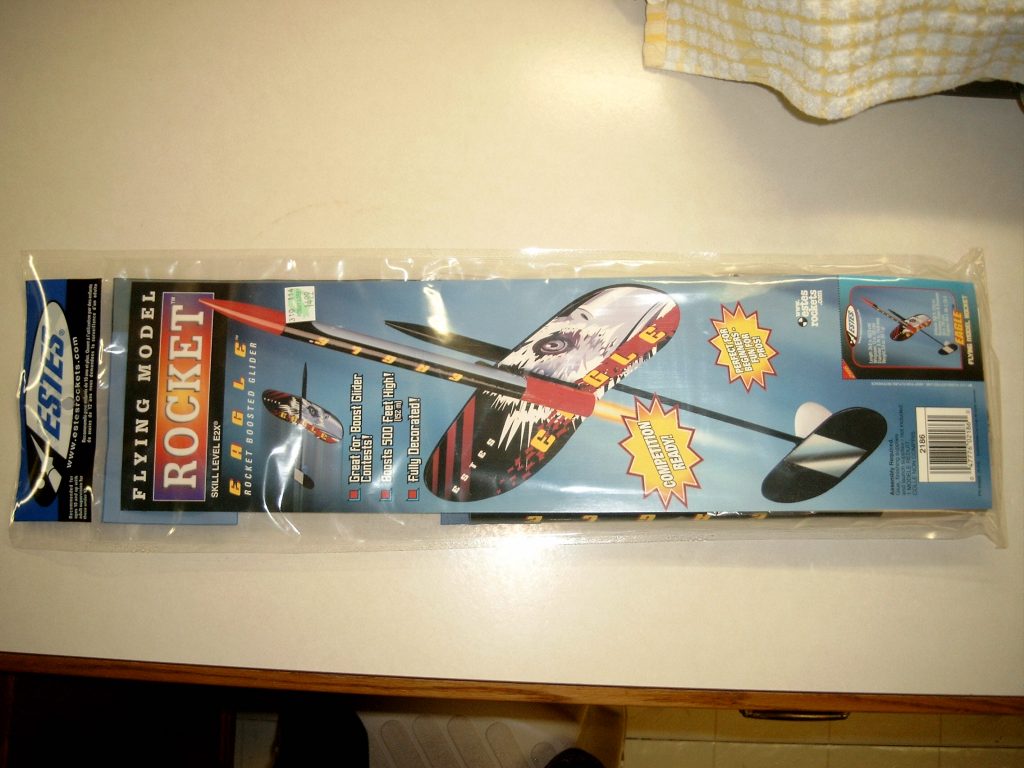
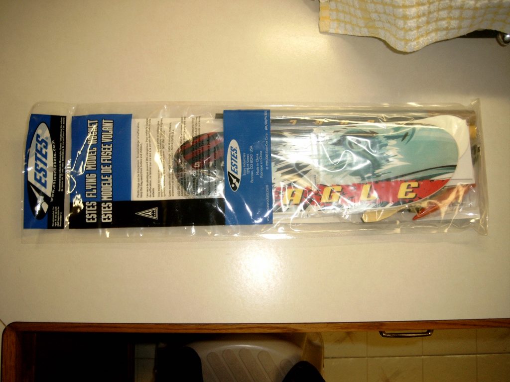
ESTES Model #2186

Description
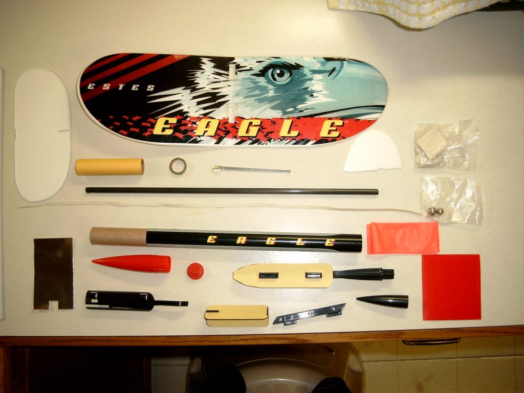
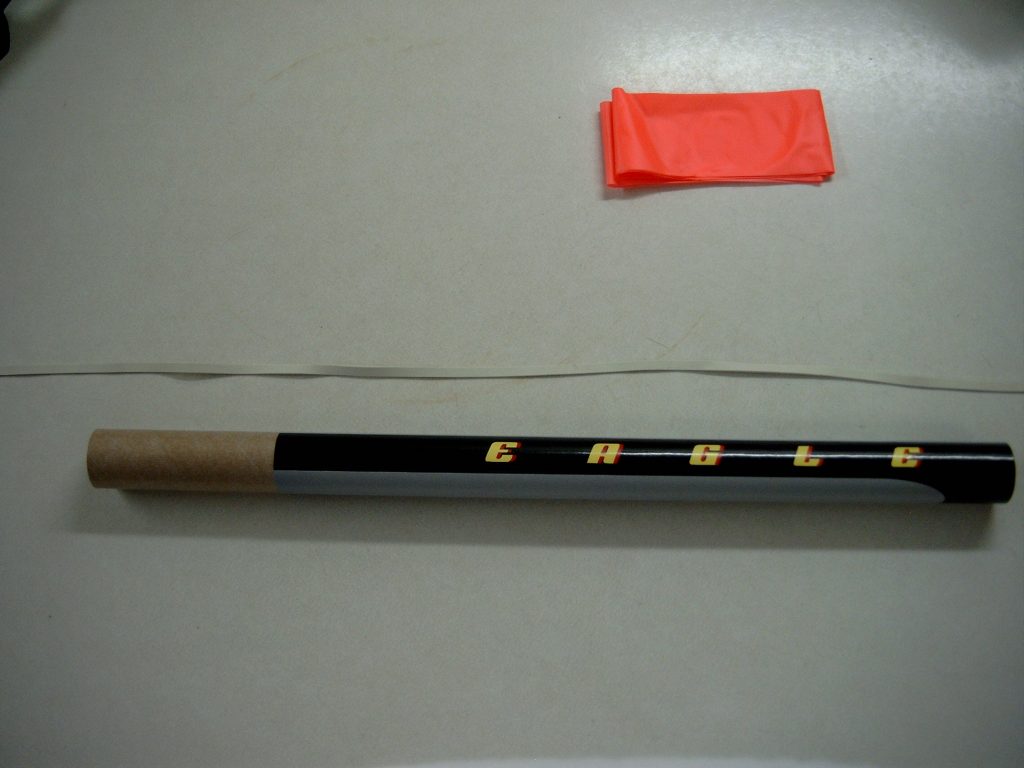
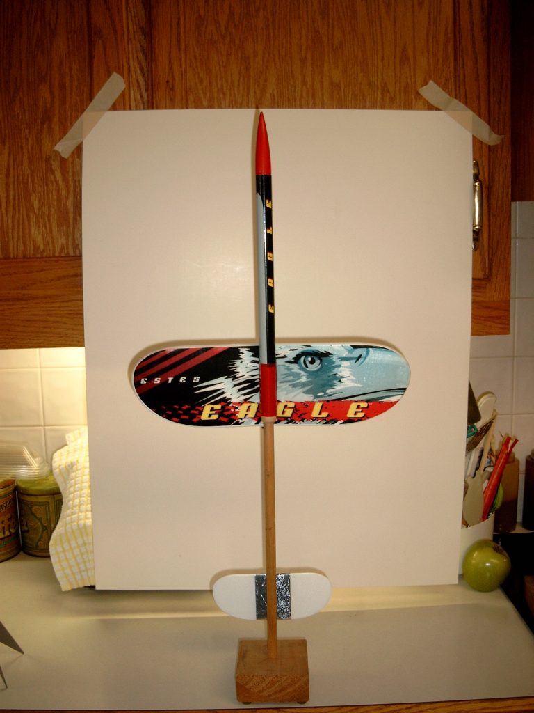
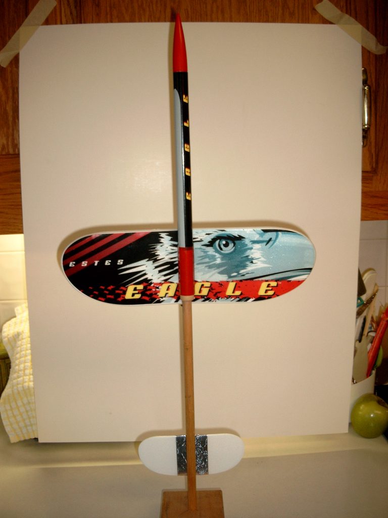
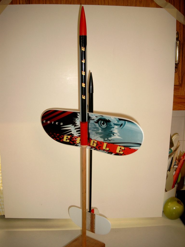
E2X – Easy to Assemble this elegant bird is an E2X – Easy to Assemble rocket. The Eagle is the perfect boost glider for beginners and a lot of fun for the experienced pro! Assembly of the Eagle Boost Glider and power pod is fairly simple and can be completed in an hour or two depending on your modeling experience. Estes has taken the complexity out of building and flying this boost glider. When powered with standard engines, the Eagle can reach over 500 feet into the air and take its time gliding down to your feet!
Additional Information
- Length: 24.8″
- Diameter: 0.74″
- Weight: 3.4 oz.
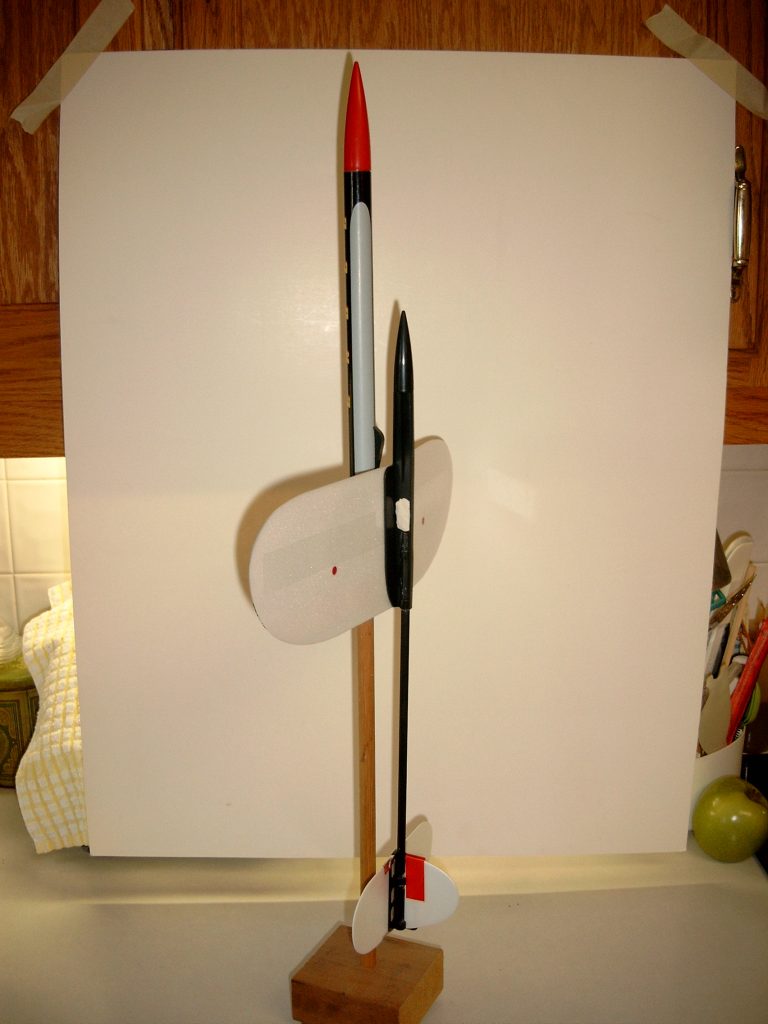
- Wingspan: 13″
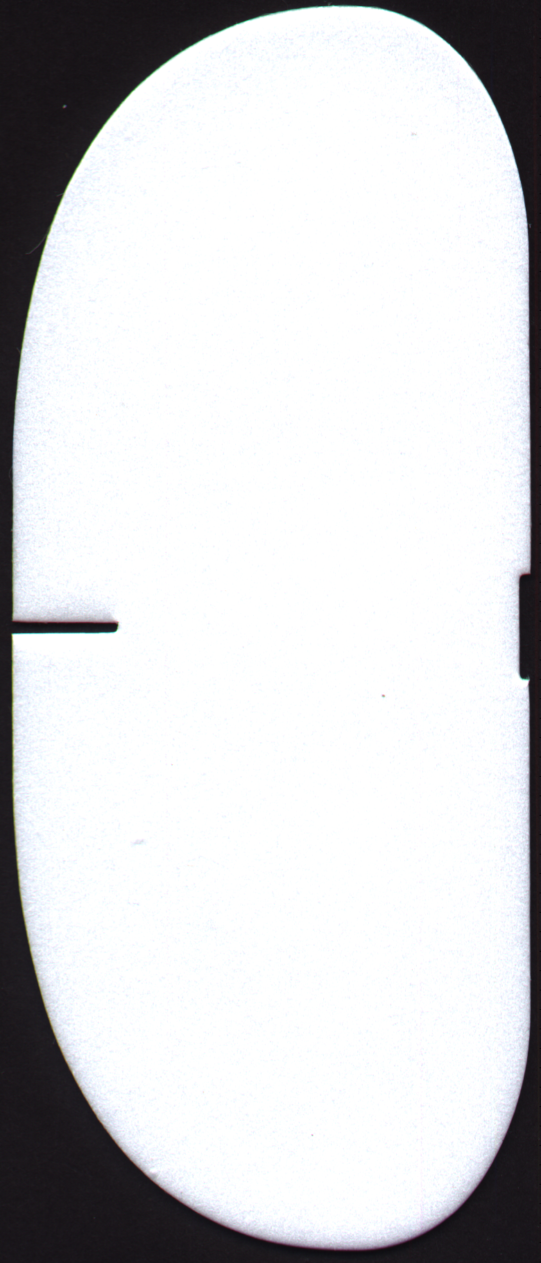
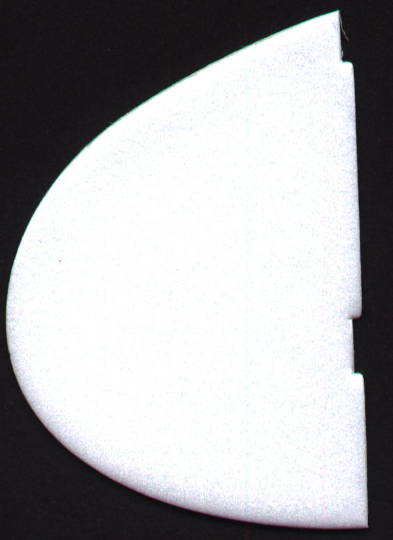
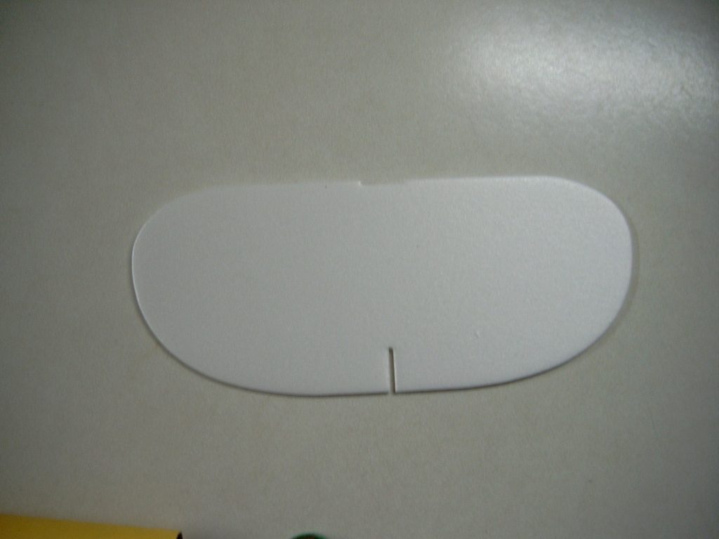
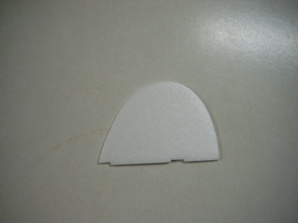
- Fins: Die Cut Foam
- Decals: Self Adhesive
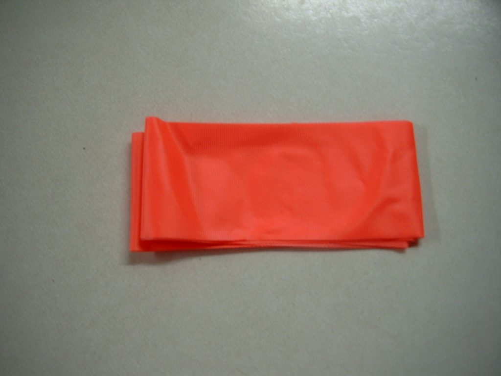
- Recovery: Streamer
- Altitude: 500′
- Recommended Motors:
- B4-2, B6-2, C6-3
Instructions
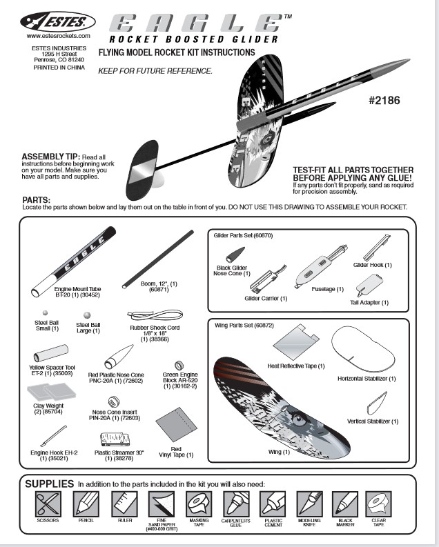
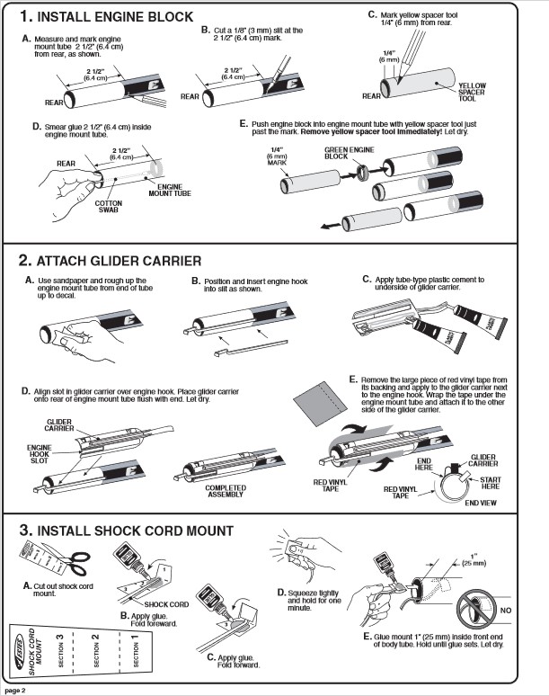
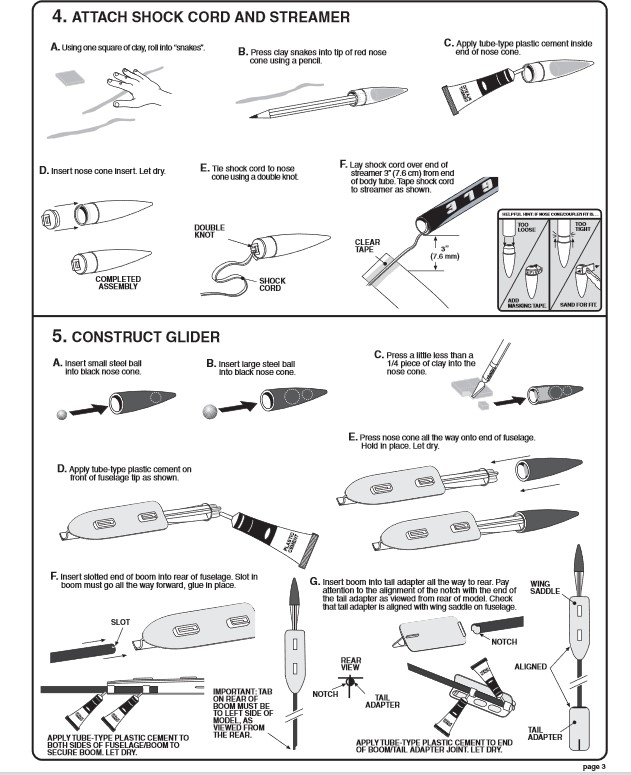
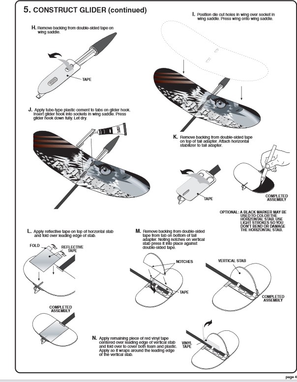
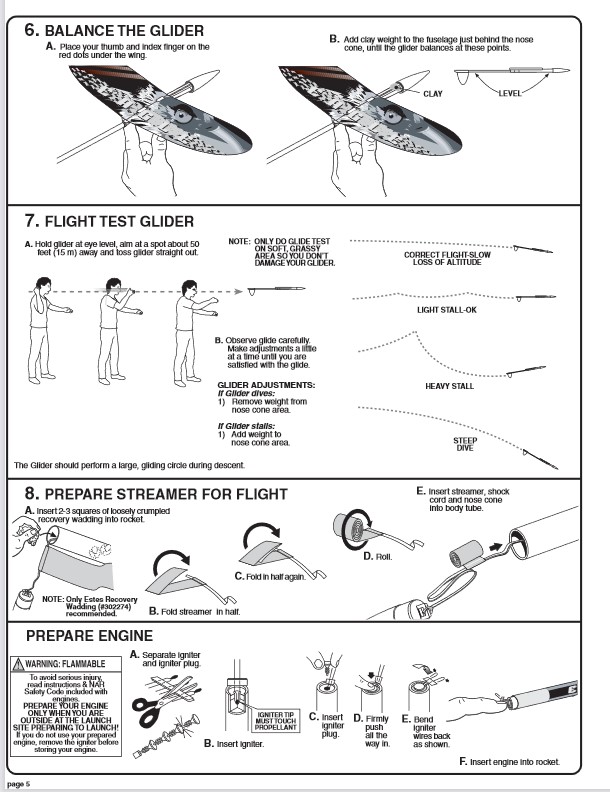
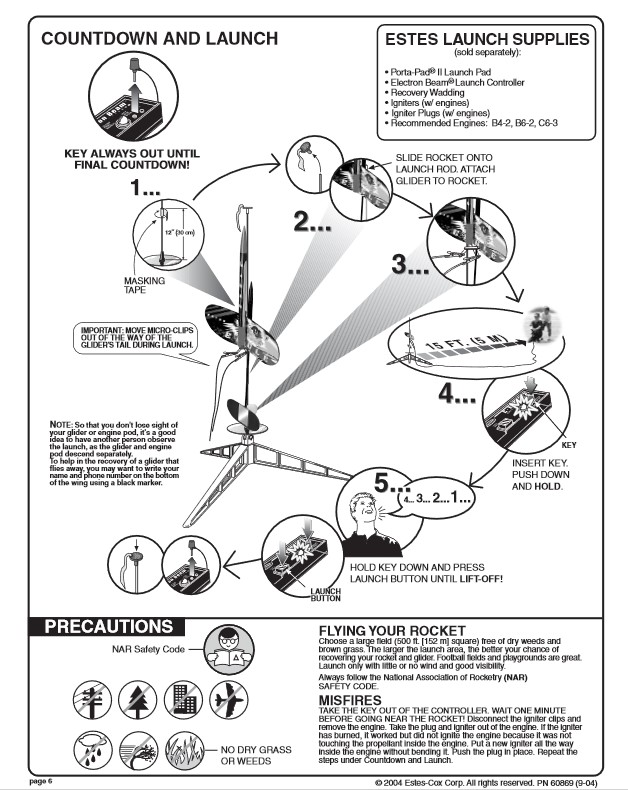
Photo Gallery


Build History
- 01/21/2006 – Purchased Estes #2186 Eagle Rocket Boost Glider from Hobby Lobby in Columbus, IN for $7.79 (Retail $15.99).
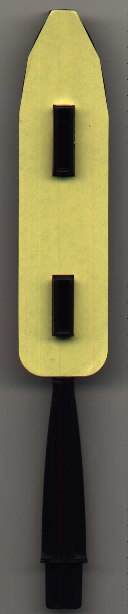
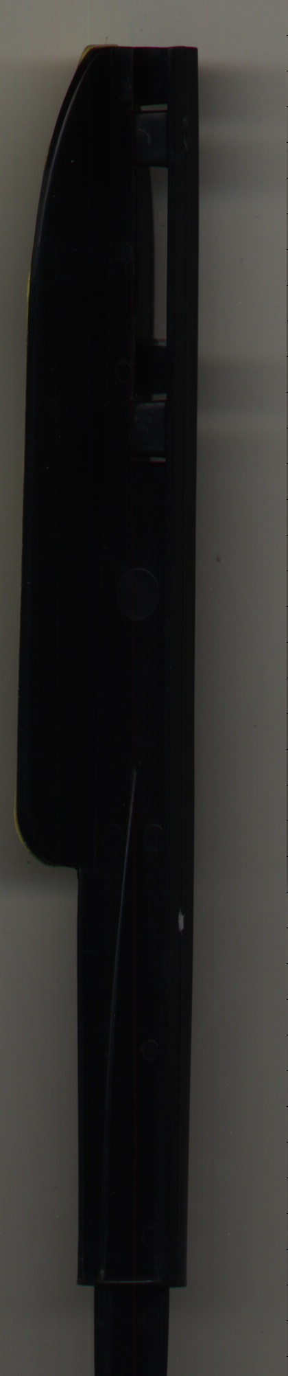
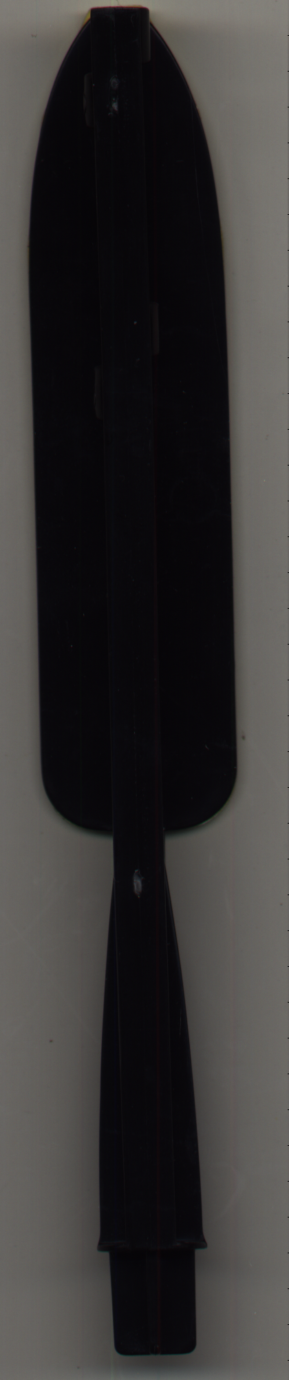
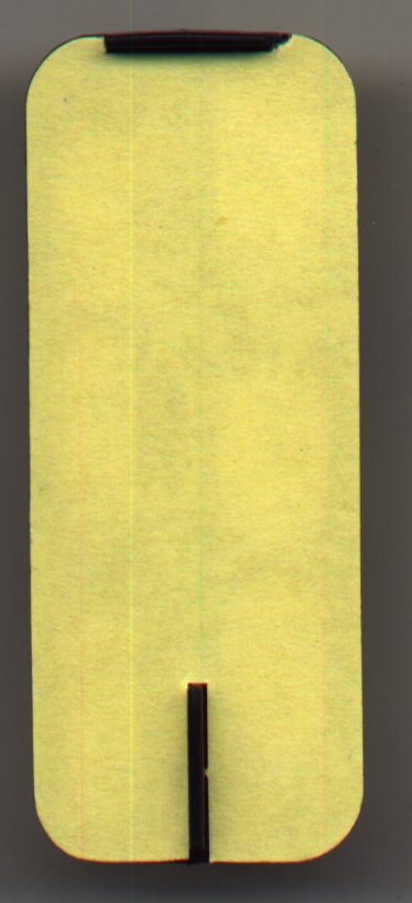
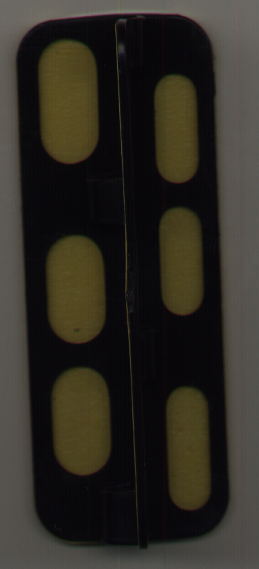
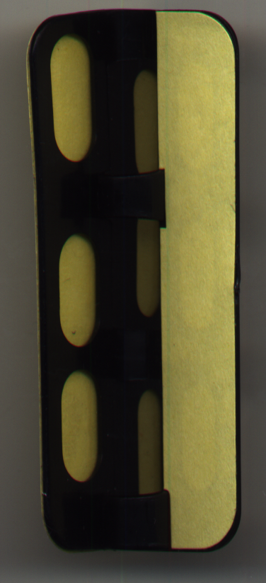
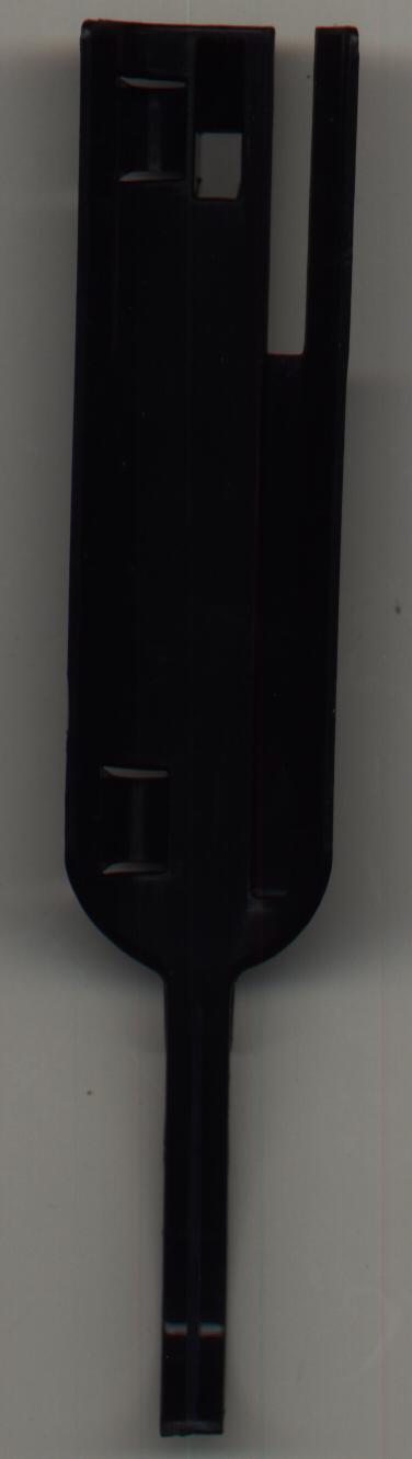
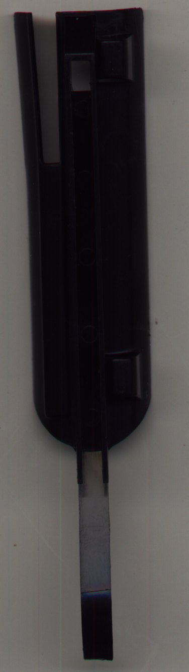
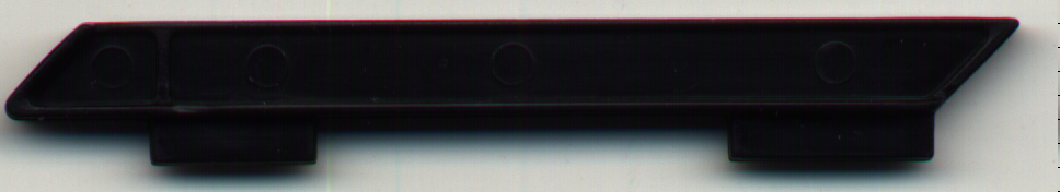
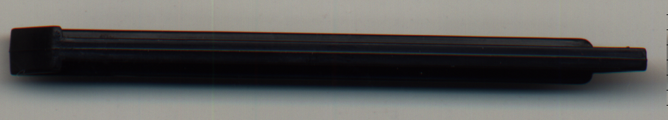
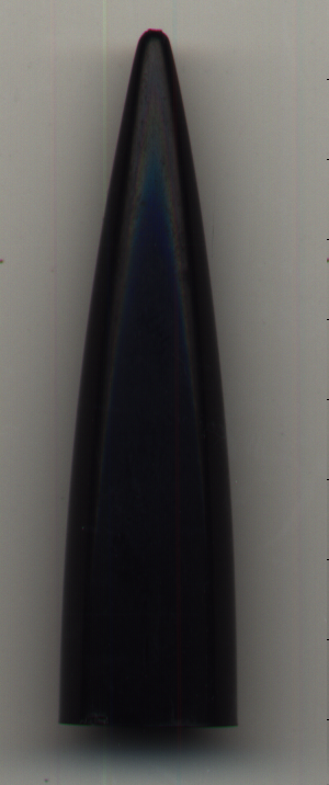
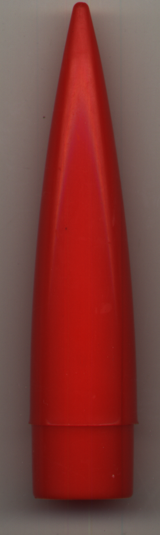
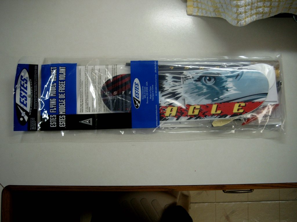
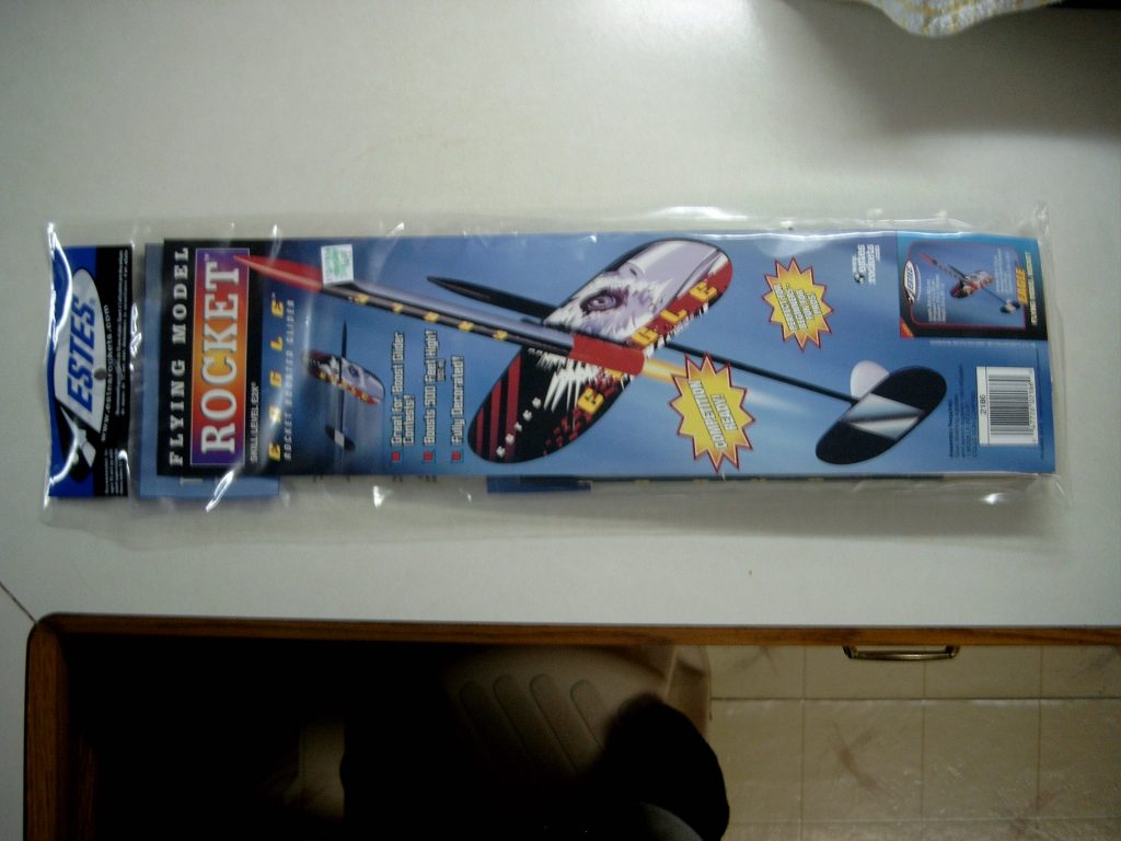
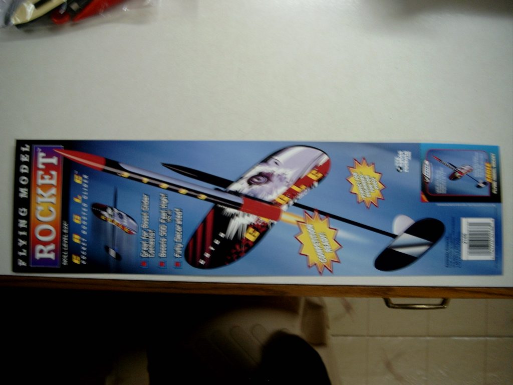
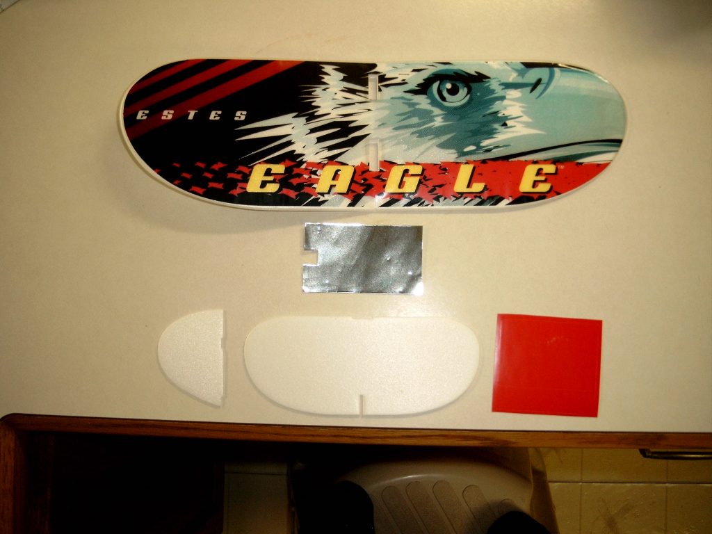
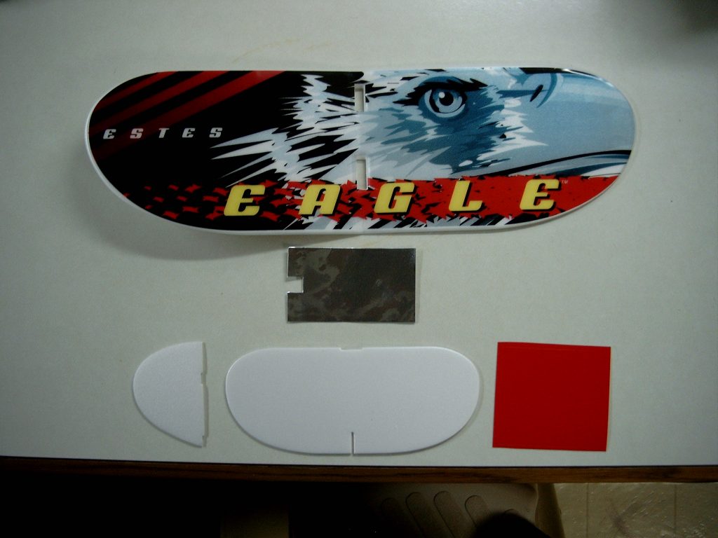
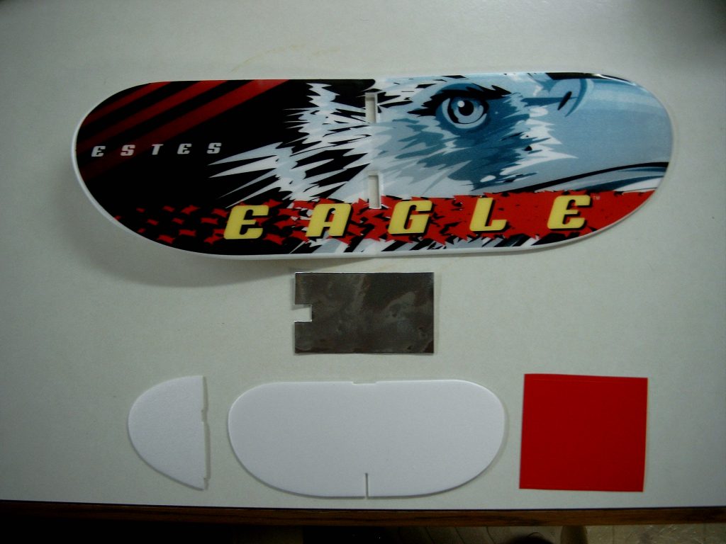
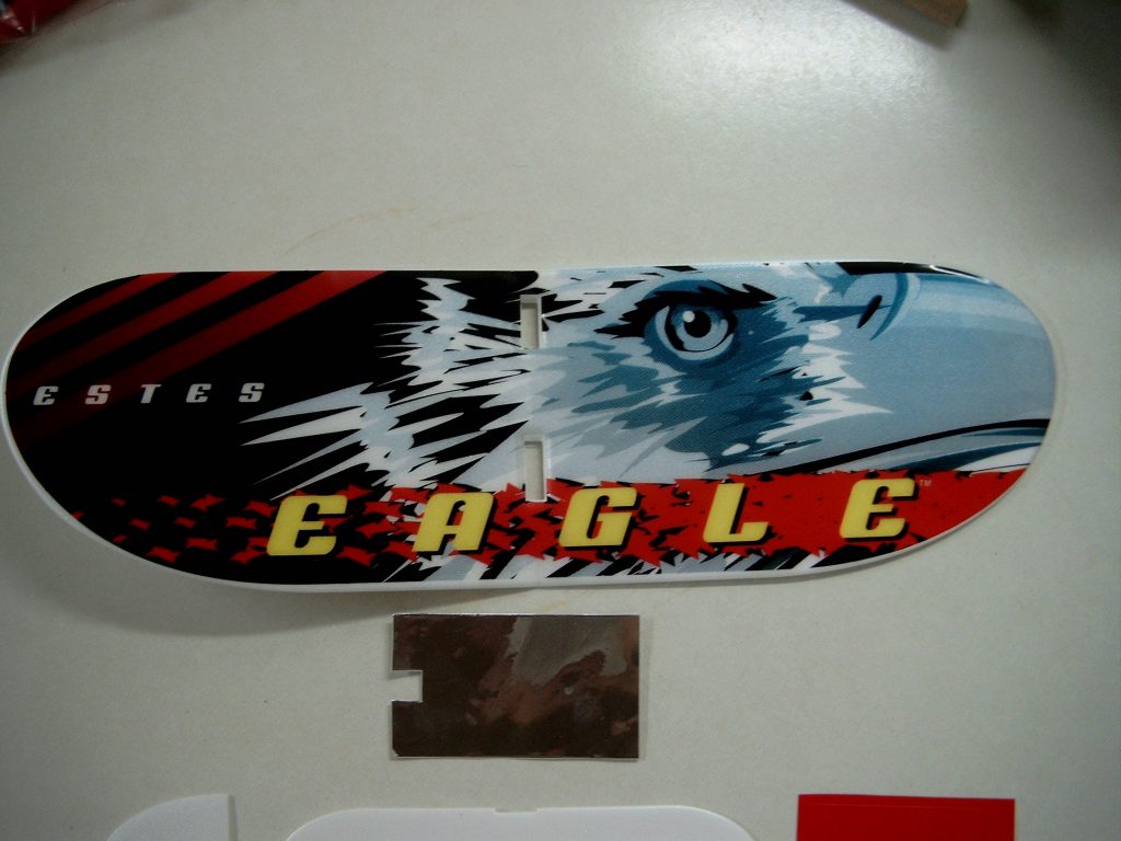
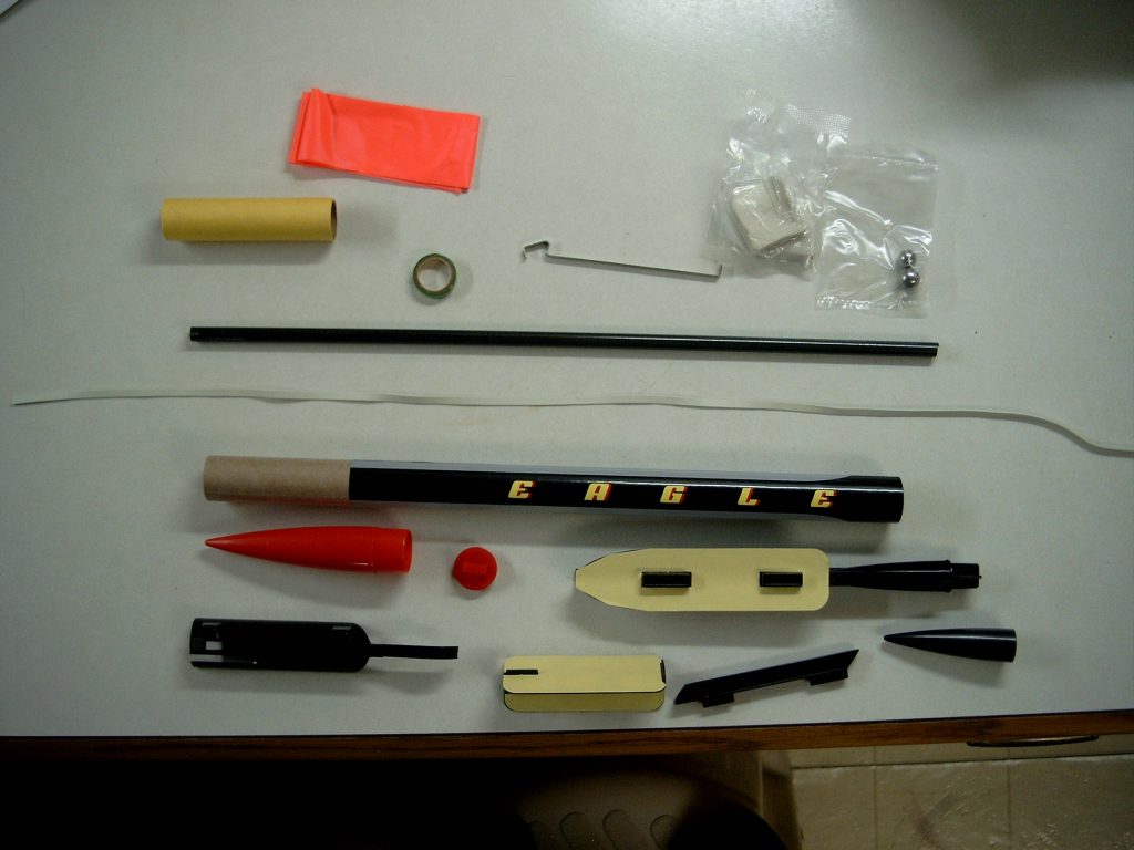
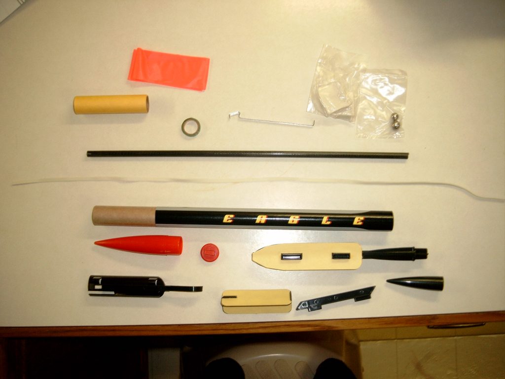
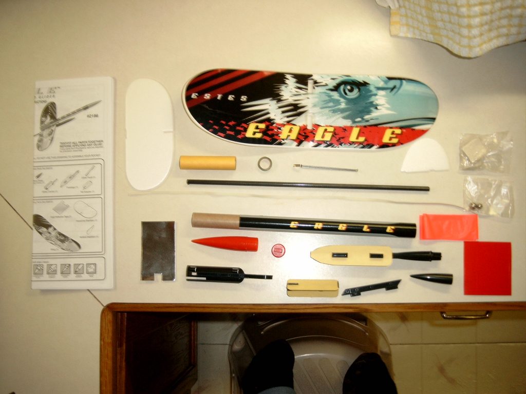
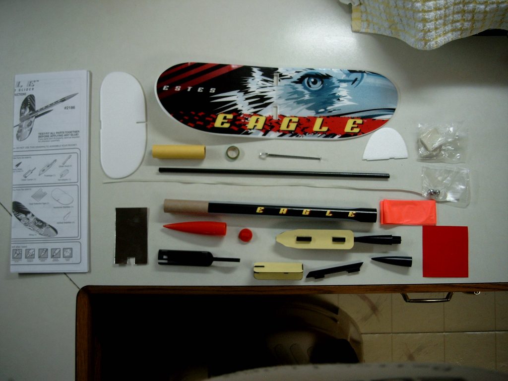
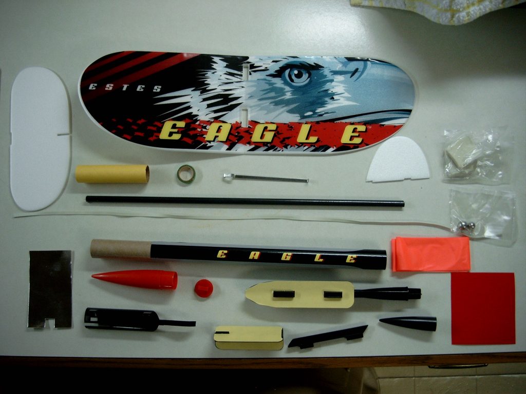
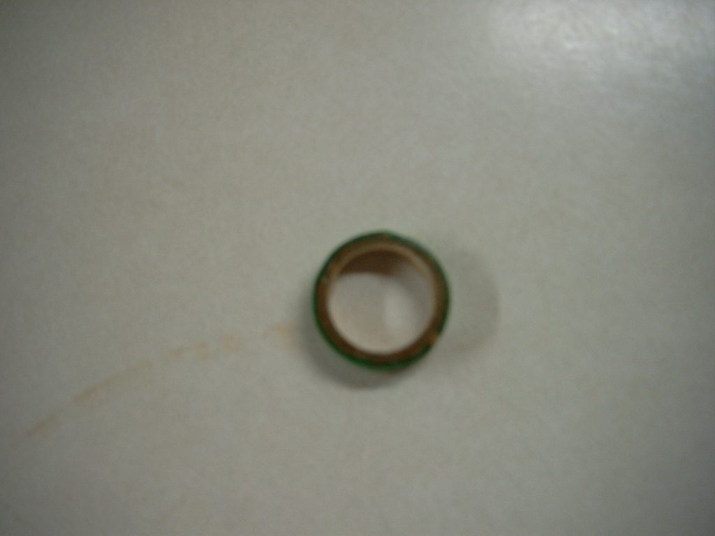
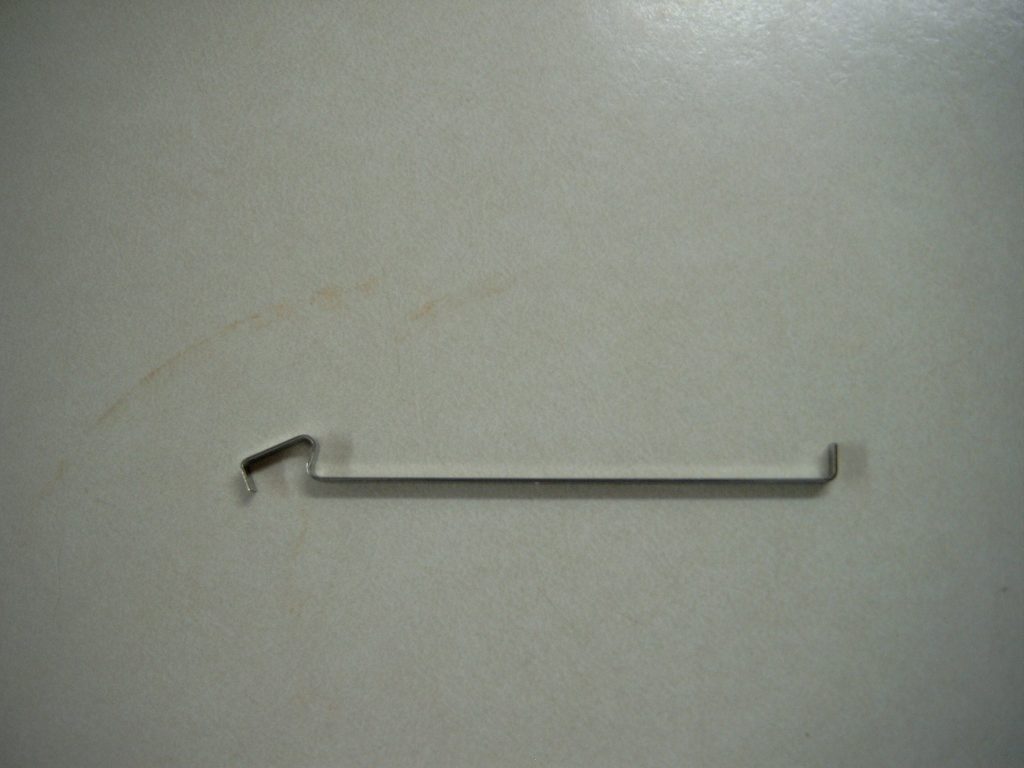
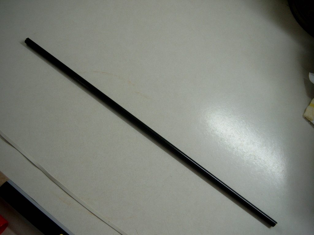
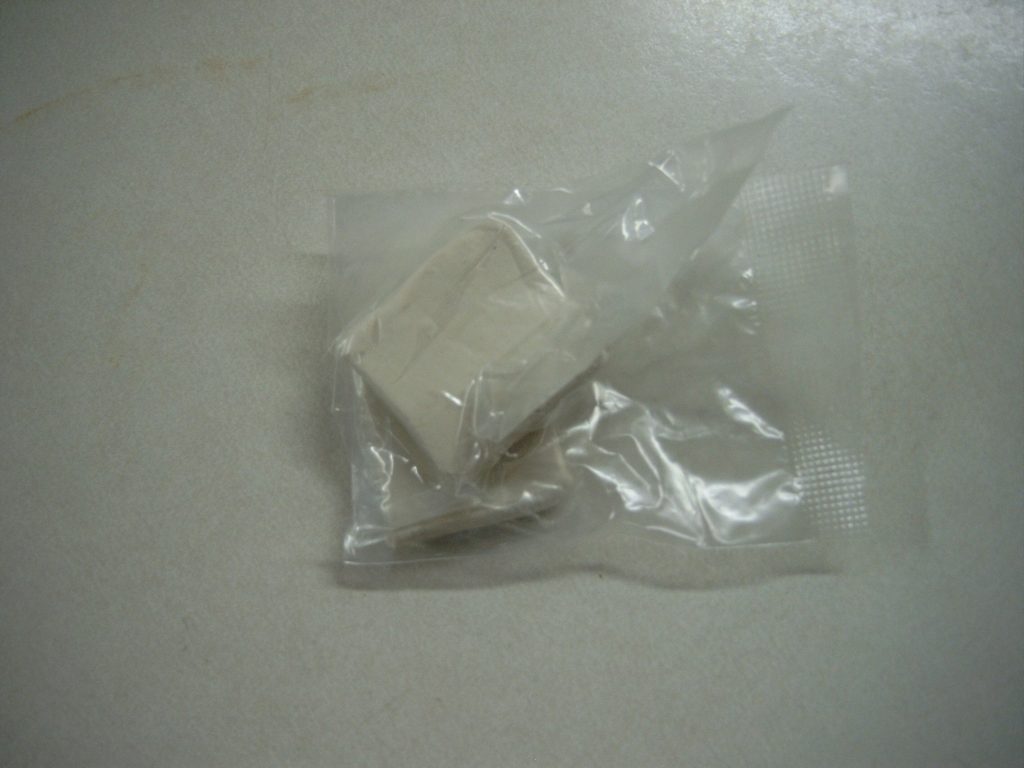
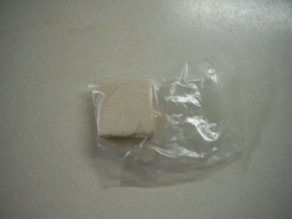
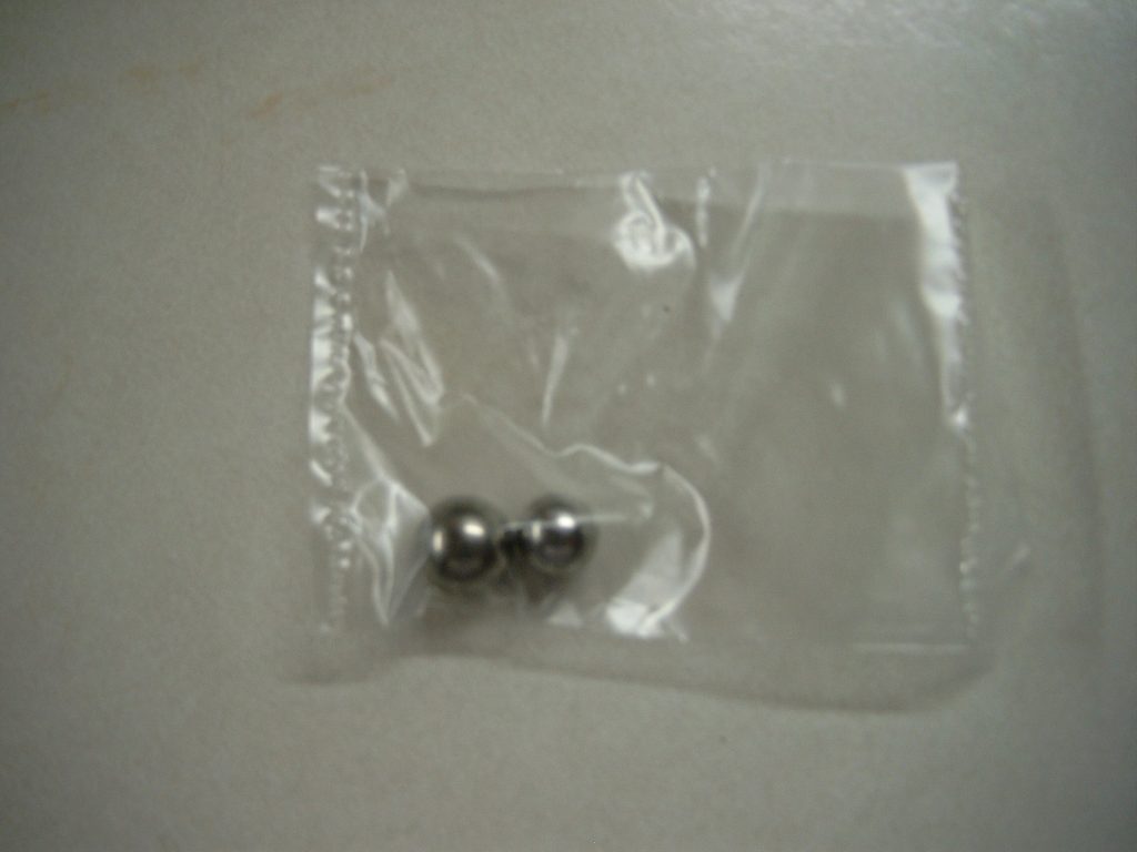
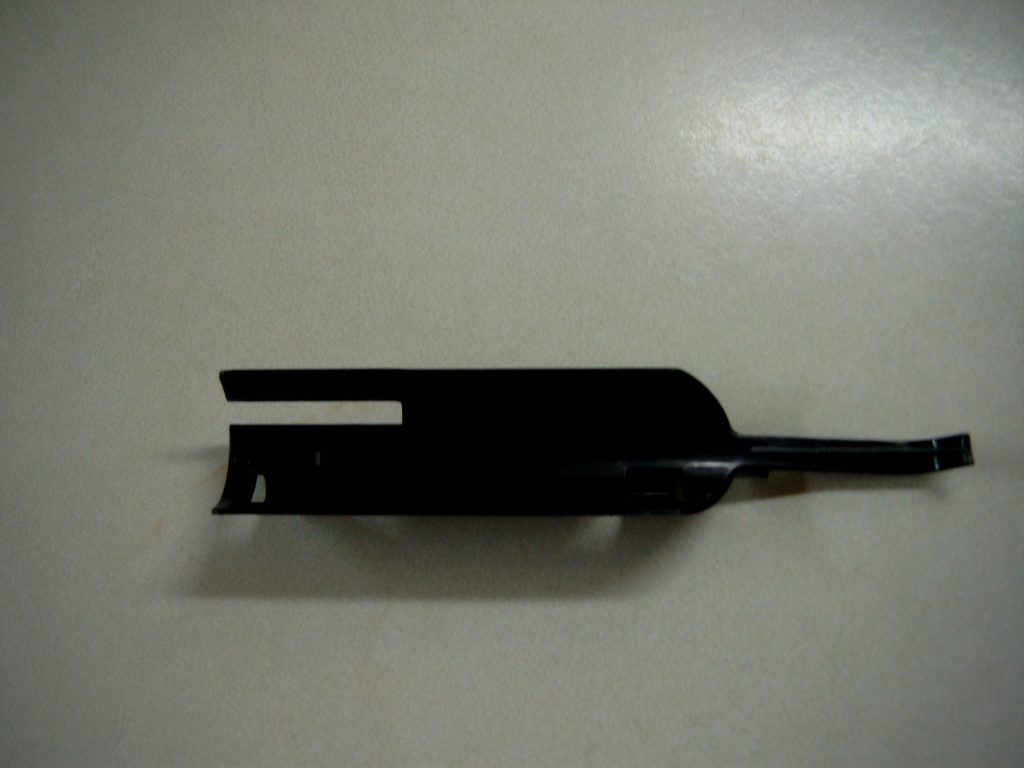
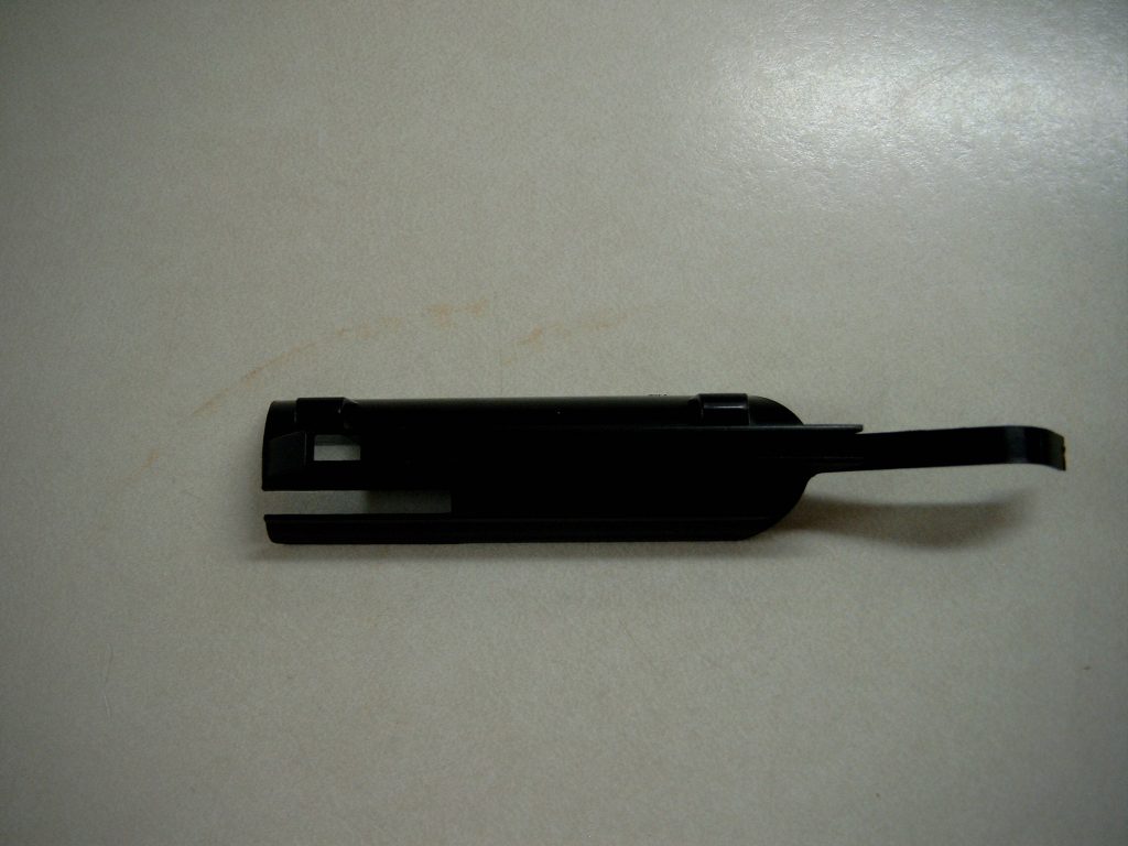
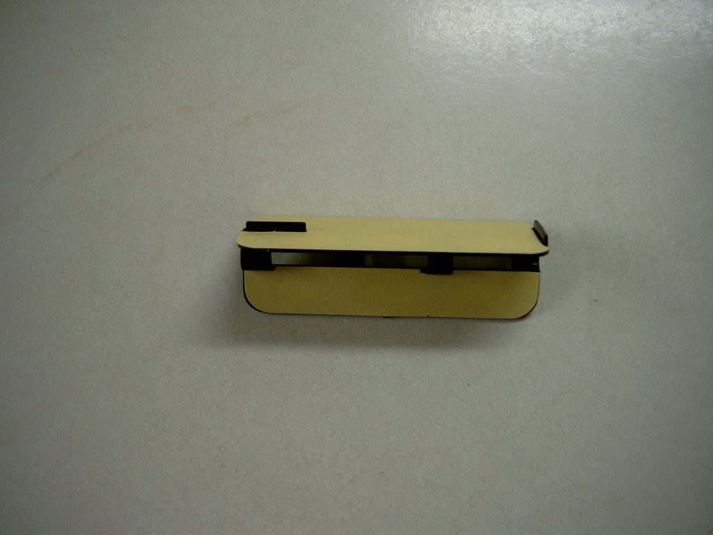
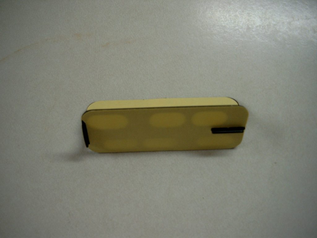
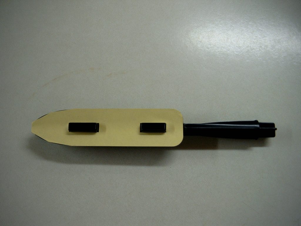
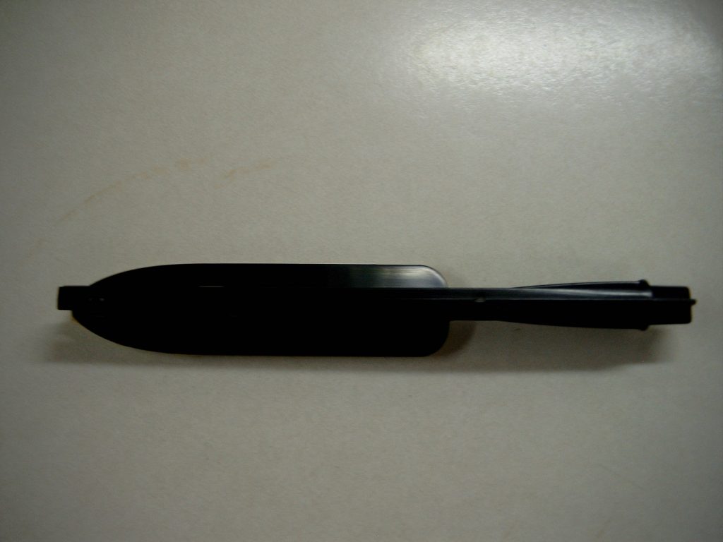
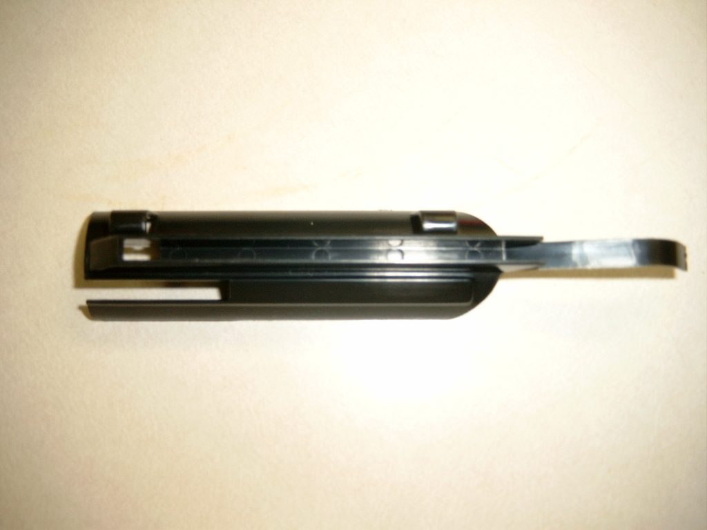
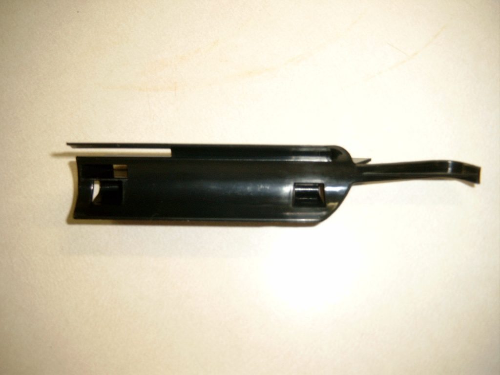
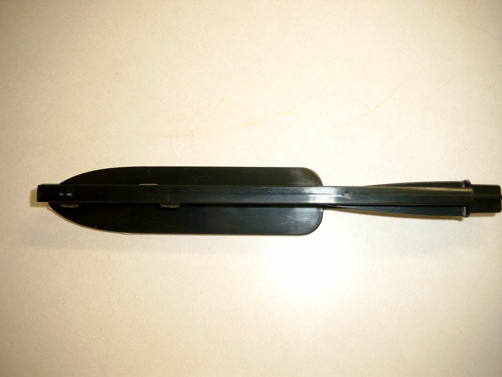
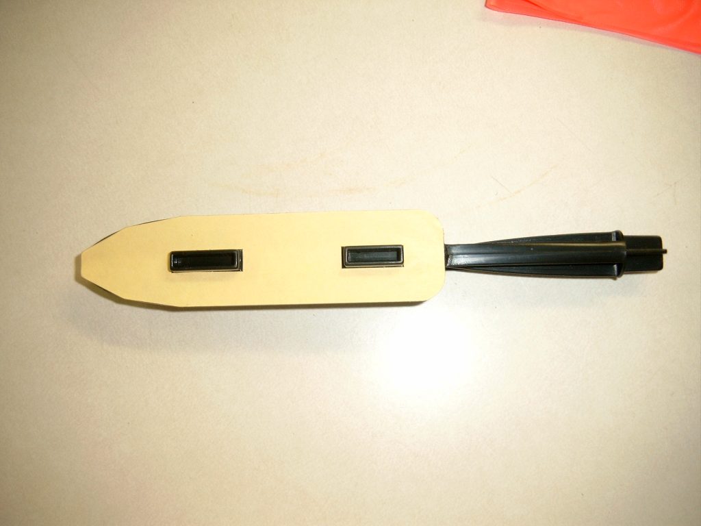
- 10/09/2005 – Took pictures of package and components.
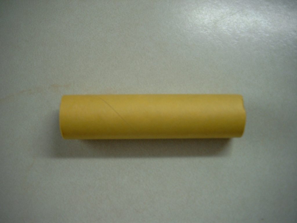
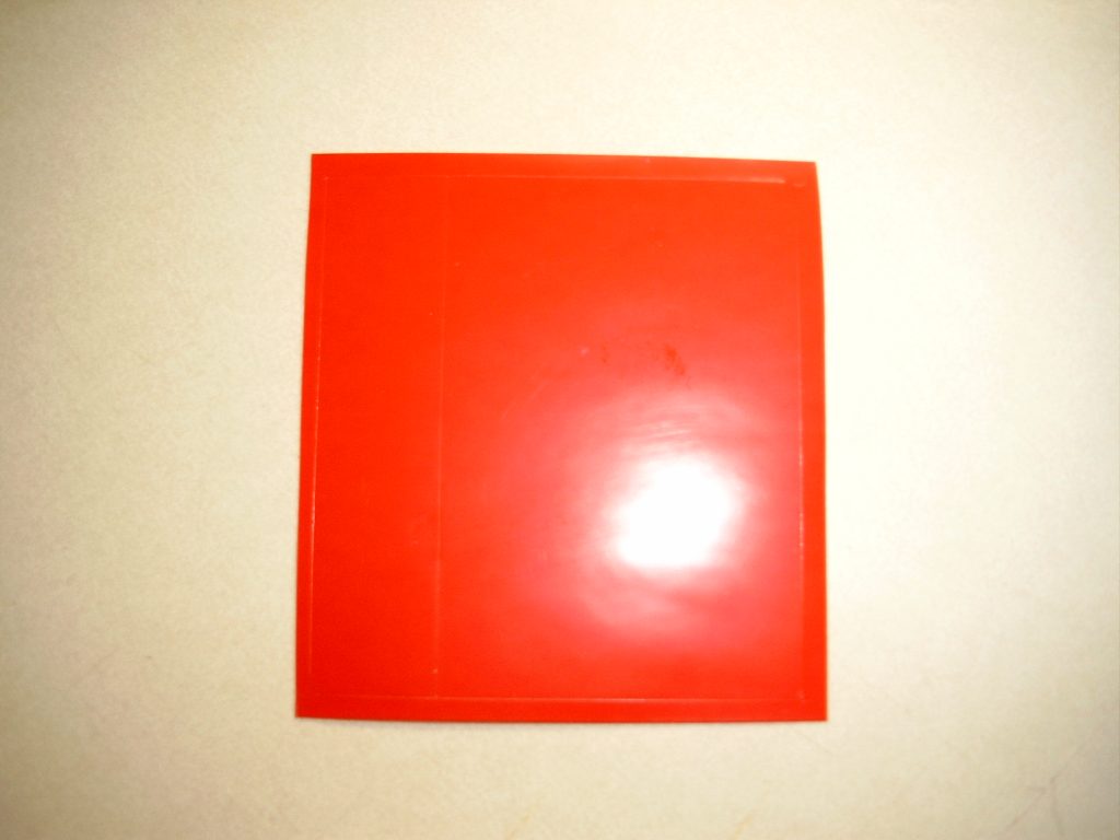
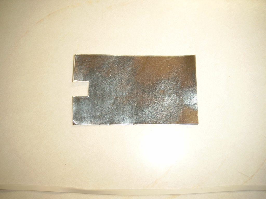
- 10/14/2005 – Measured engine tube 2-1/2″ from aft end and cut a 1/8″ slit. Marked yellow engine spacer tube 1/4″ from aft end. Applied glue 2-1/2″ from aft end of engine mount tube. Slid green block into place using yellow engine spacer tube. Using 1 square of clay, rolled it into a snake and pushed it into the red nose cone as far forward as possible. Cemented nose cone base into nose cone. Glued shock cord into shock cord mount and then inside forward end of body tube by about 2″. Placed a small steel ball, then a larger steel ball and then 1/4 of a clay block into the black nose cone. Cemented the front of the fuselage into the black nose cone. Attached the motor retainer and hen cemented the glide carrier to the motor mount tube placing the glider carrier over thr retainer clip and flush with the end of the tube. Wrapped a piece of vinyl tape around the engine mount tube and glider carrier. Inserted the 12″ boom with the slot end into the rear of the fuselage so it goes all the way forward and then cemented it in place. Inserted the boom into the tail adapter so the notch was to the left. Removed the backing from the wing saddle and positioned it over the die cut hole and pressed the wing in place. Applied cement to the glider hook tabs and inserted into the wing saddle so the angled side faced forward. Removed backing fron the tail adapter and placed the horizonal stabalizer in place. Removed the backing from the reflective tape and placed it over the horizonal stabalizer so the tabs folded over the foam. Removed the backing from the vertical stabalizer on the tail section and pressed the foam unit into place assuring the notches lined up. The 1″ x 30″ streamer was taped 3″ from the engine mount. The glider was trimmed to fly correctly. This completes construction of Estes #2186 Eagle Boost Glider.
Flights
| Date | Location | # | Motor | Comments |
Leave a Reply
You must be logged in to post a comment.