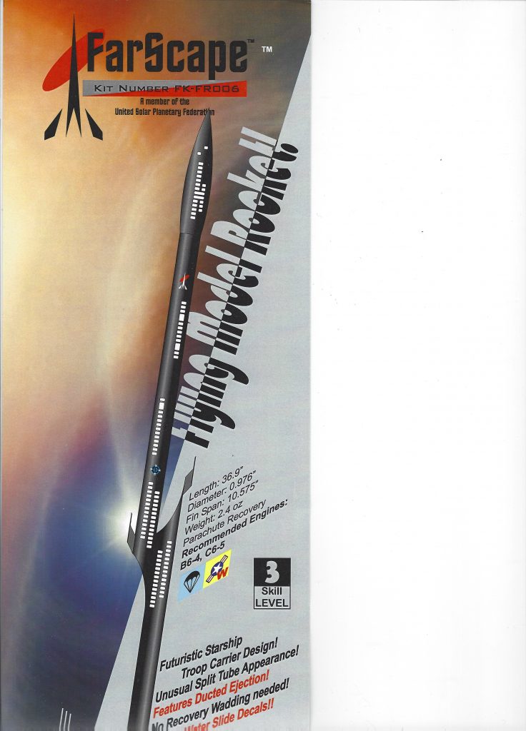
Model #FR006
Description
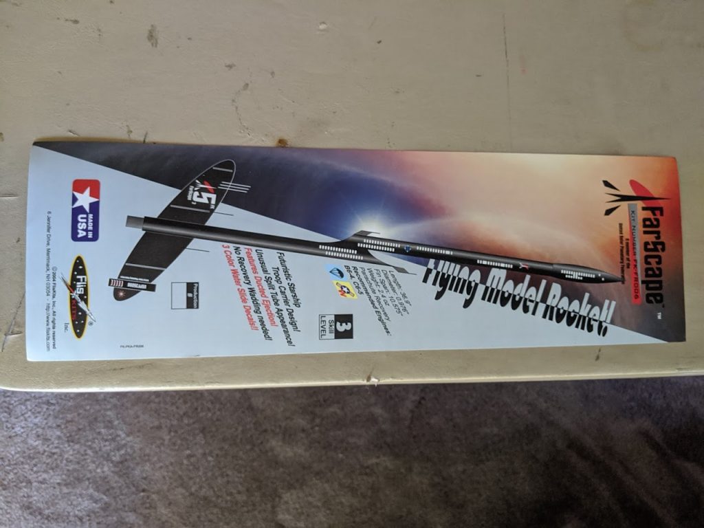
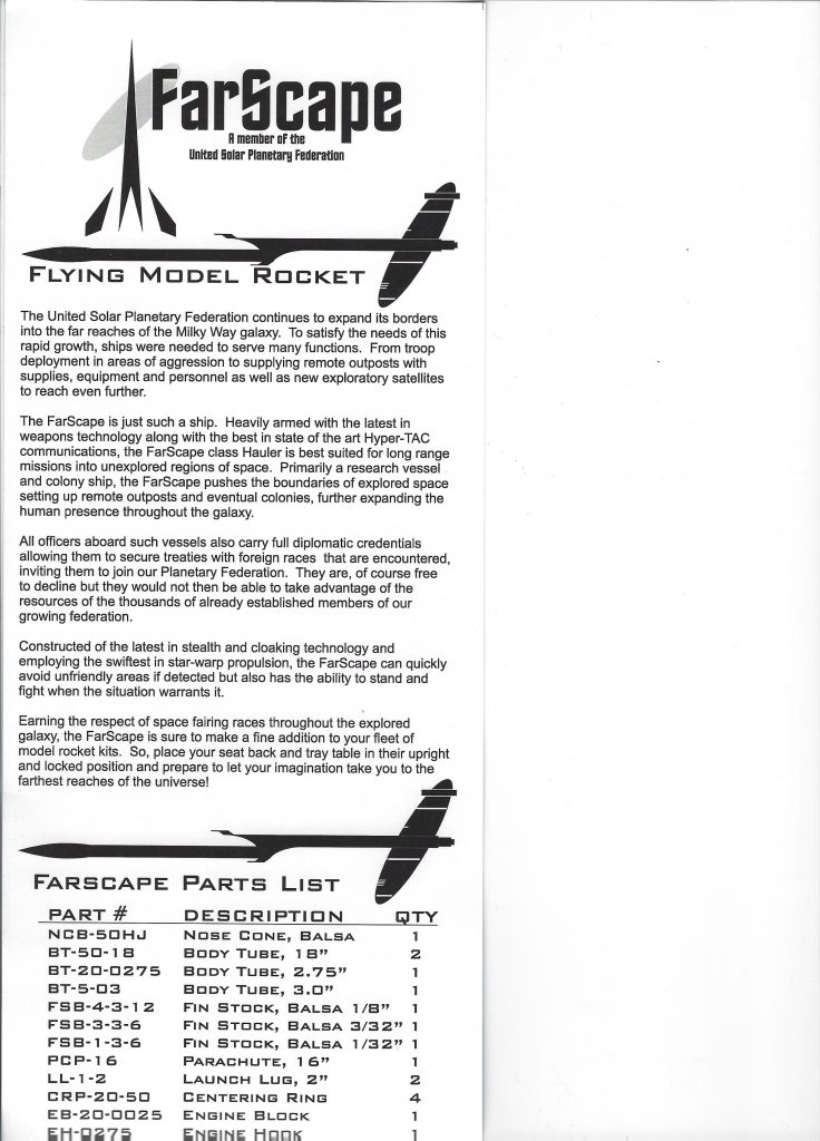
The United Solar planetary Federation continues to expand its borders into the far reaches of the Milky way galaxy. To satisfy the needs of the rapid growth, ships were needed to serve many functions. Trom troop deployment in areas of aggression to supplying remote outposts with supplies, equipment and personnel as well as new exploratory satellites to reach even farther.
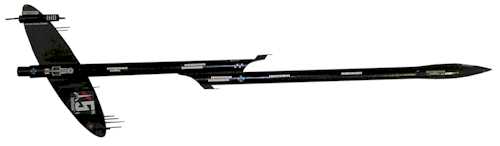
The FarScape is just such a ship. Heavily armed with the latest in weapons technology along with the best in state of the art Hyper TAC communications, the FarScape class Hauler is best suited for long range missions into unexplored regions of space. Primarily a research vessel and colo9ny ship, the FarScape pushes the boundaries of explored space setting up repote outposts and eventual colonies, further expanding the human presence throughout the galaxy.
Additional Information
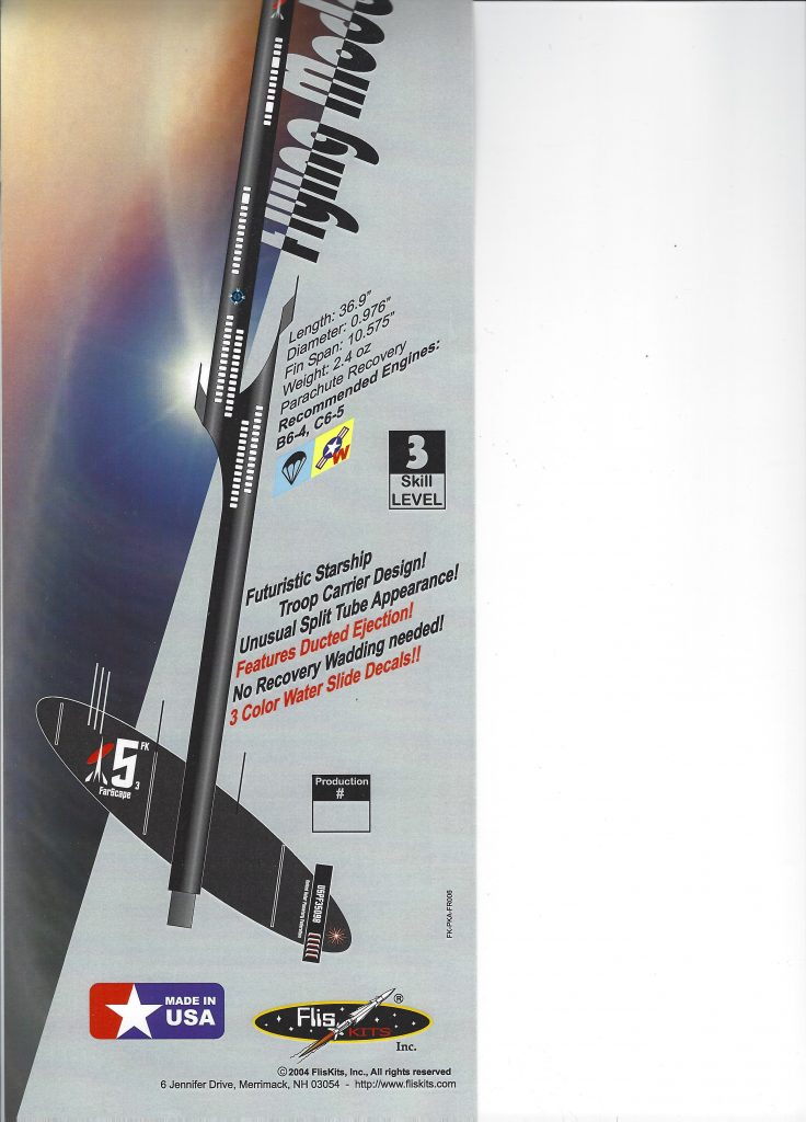
- Length: 36.9″
- Diameter: 0.976″
- Weight: 2.4 oz.
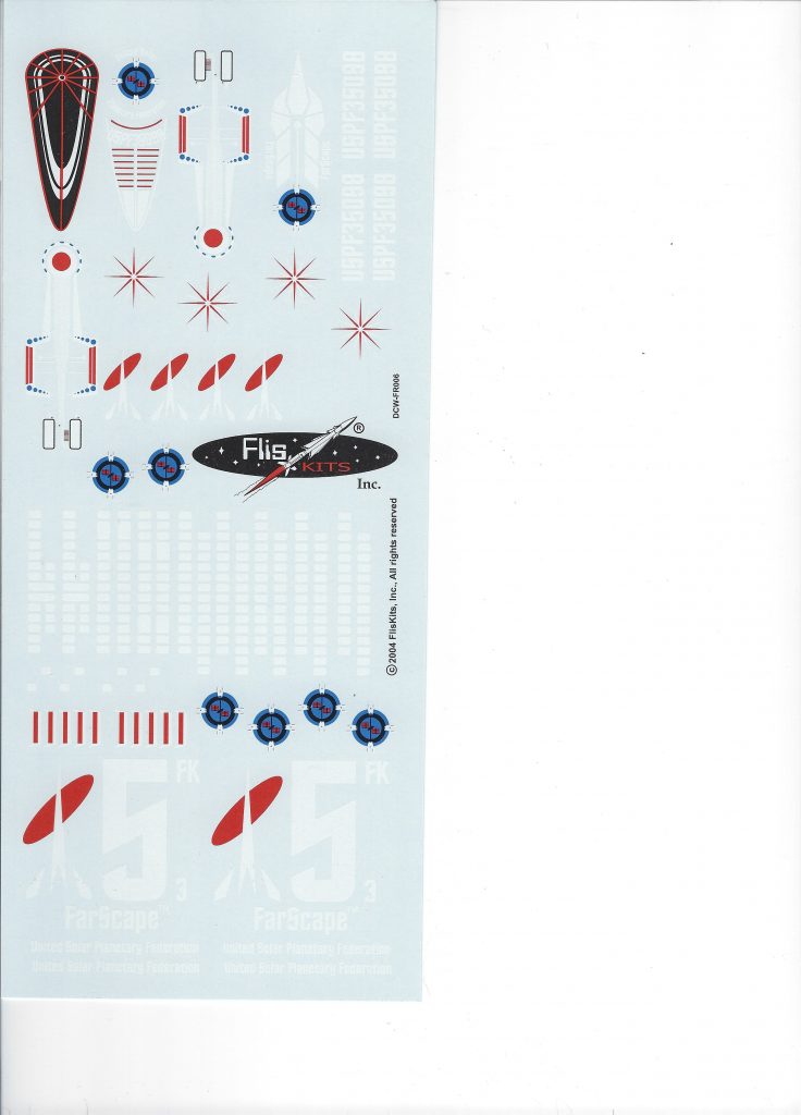
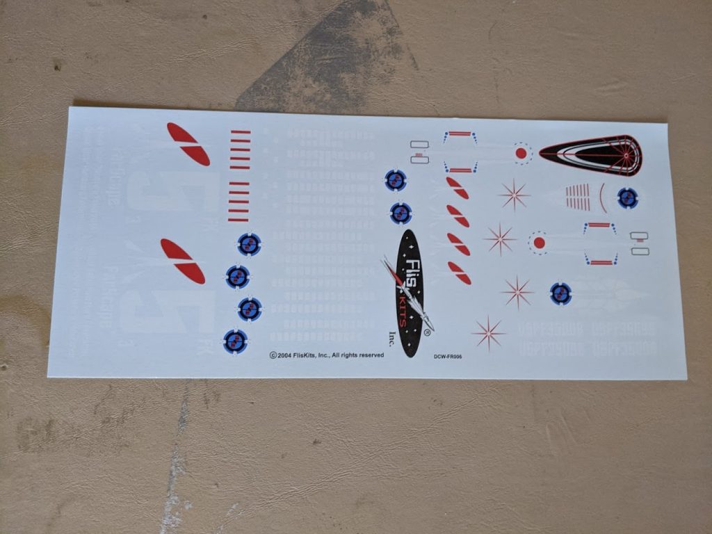
- Decals: Water Slide
- Recovery: 16″ Parachute
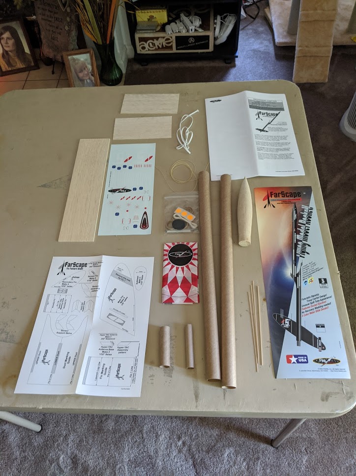
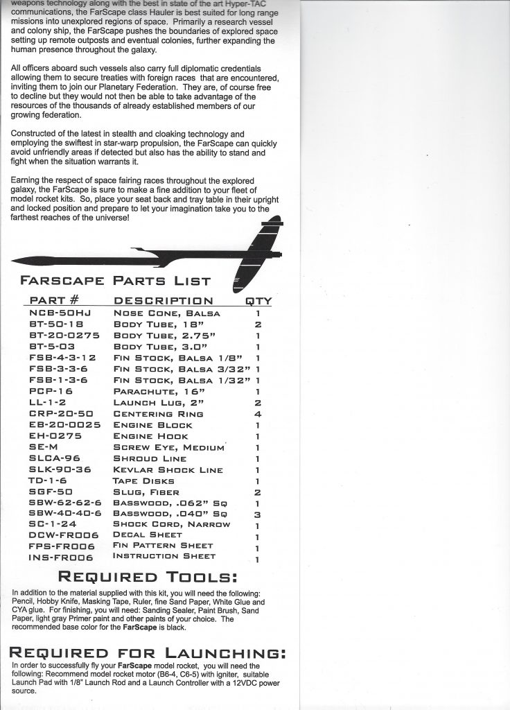
- Parts List
- Nose Cone Balsa – NCB-50H
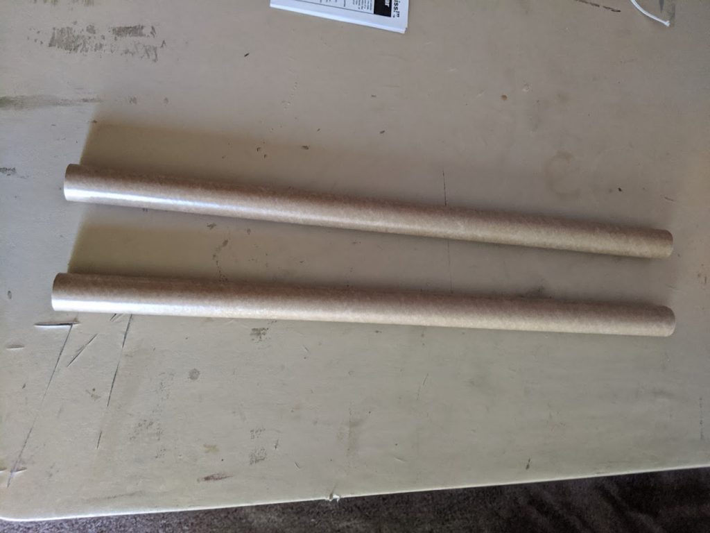
- Body Tubes (2) (18″) – BT-50-1B
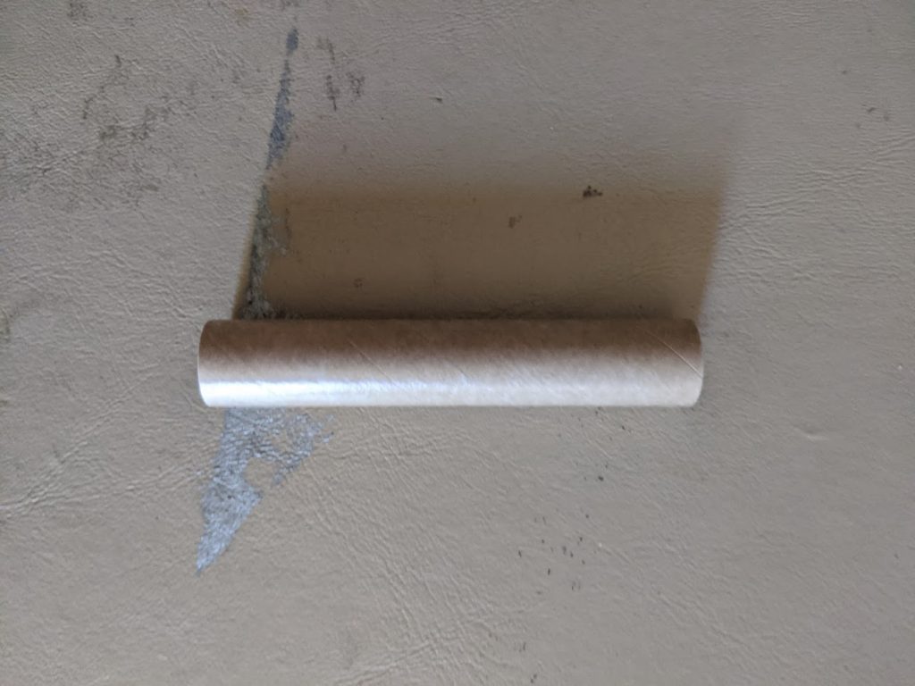
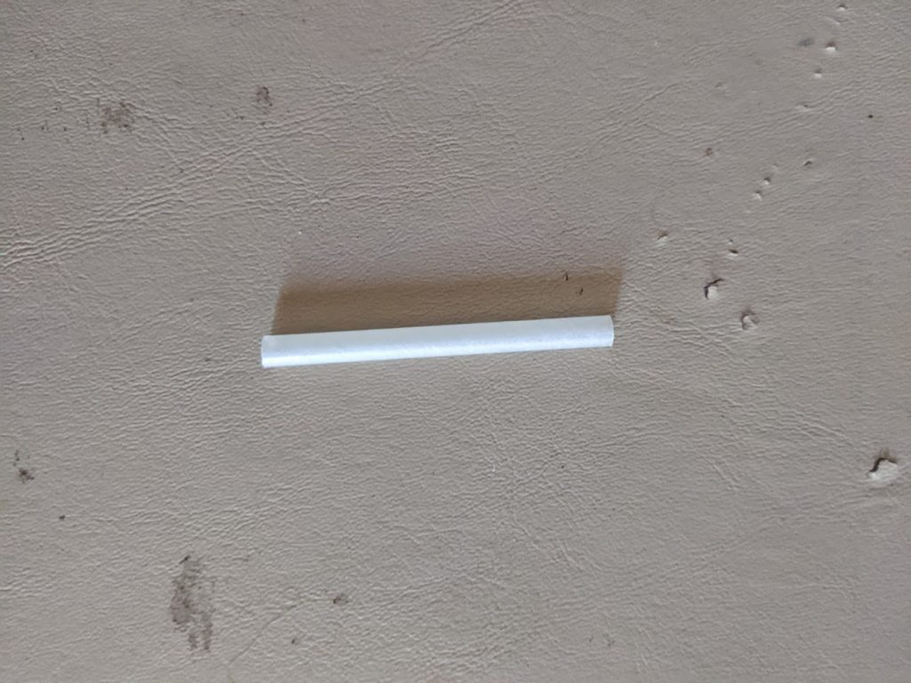
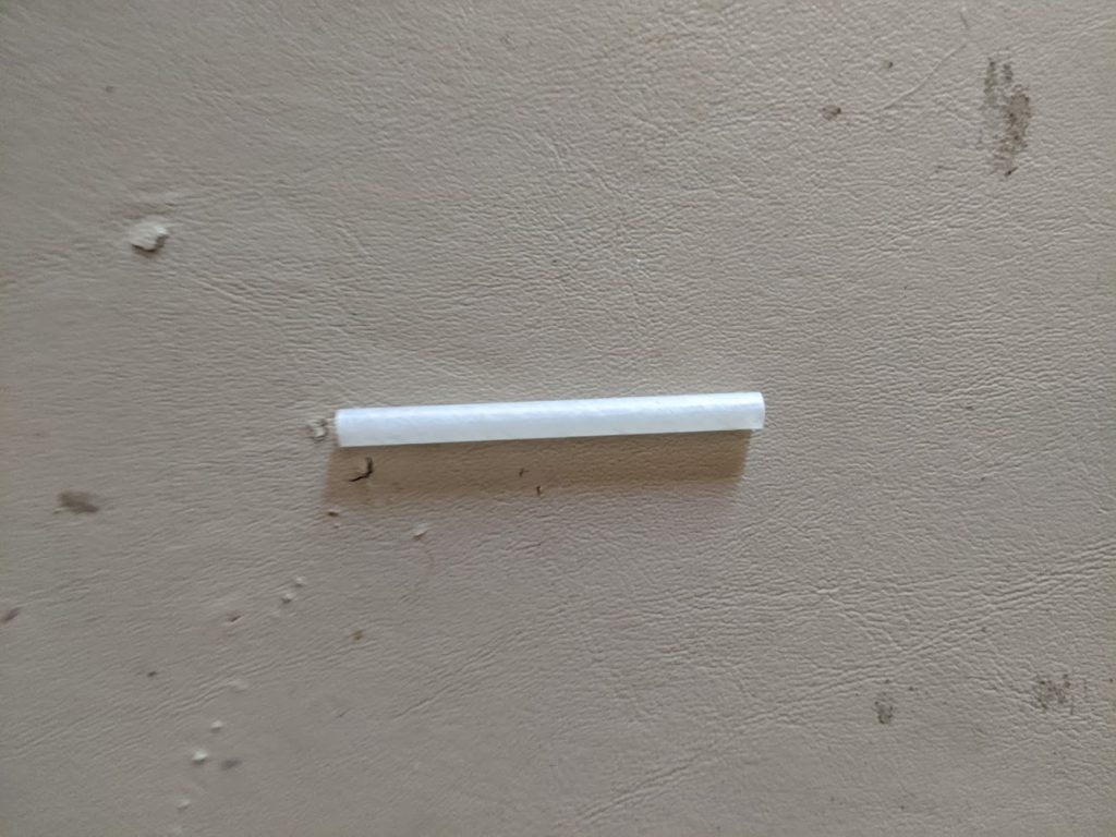
- Body Tube (2.75″) – BT-20-2075
- Body Tube (3″) – BT-5-03
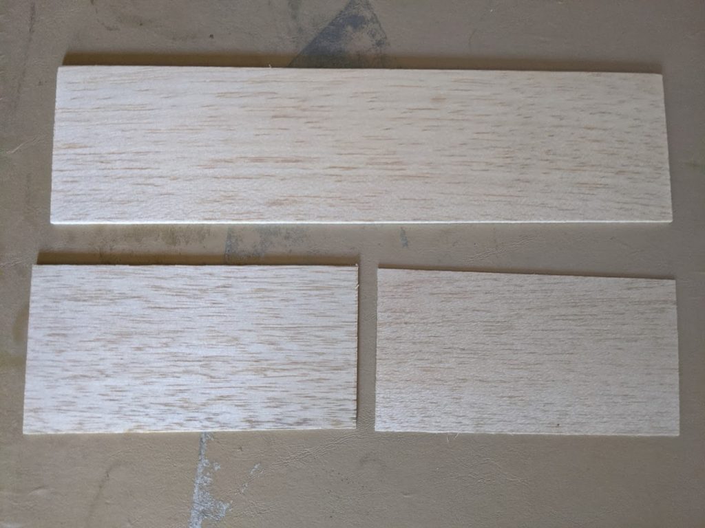
- Fin Stock Balsa Sheet 1/8″ – BFS-4-3-1 2
- Fin Stock Balsa Sheet 3/32″ – BFS-3-3-6
- Fin Stock Balsa Sheet 1/32″ – FSB-1-3-6
- Parachute (16″) – PCP-16
- Launch Lug (2) (2″) – LL-1-2
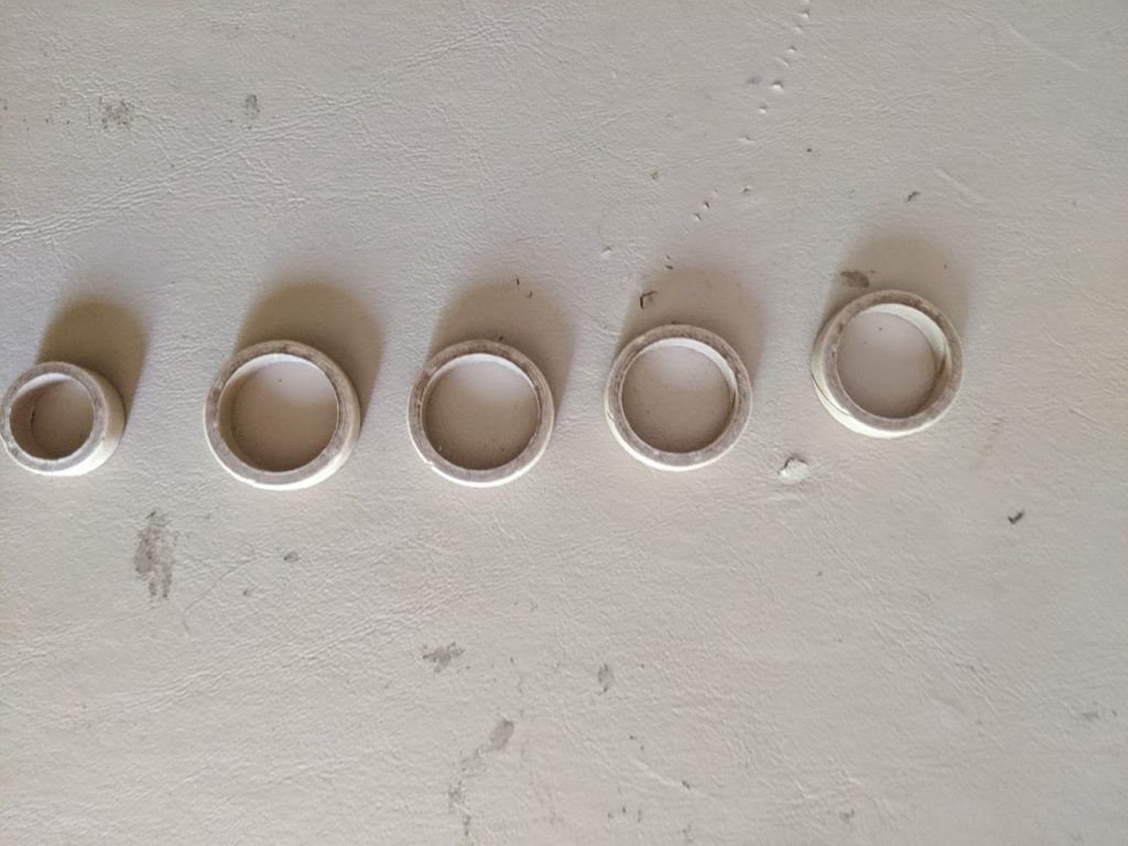
- Centering Rings (4) – CRP-20-50
- Engine Block – EB-20-0025
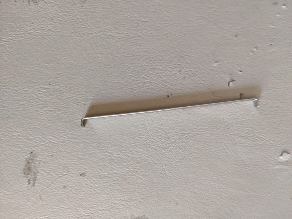
- Engine Hook – EH-0275
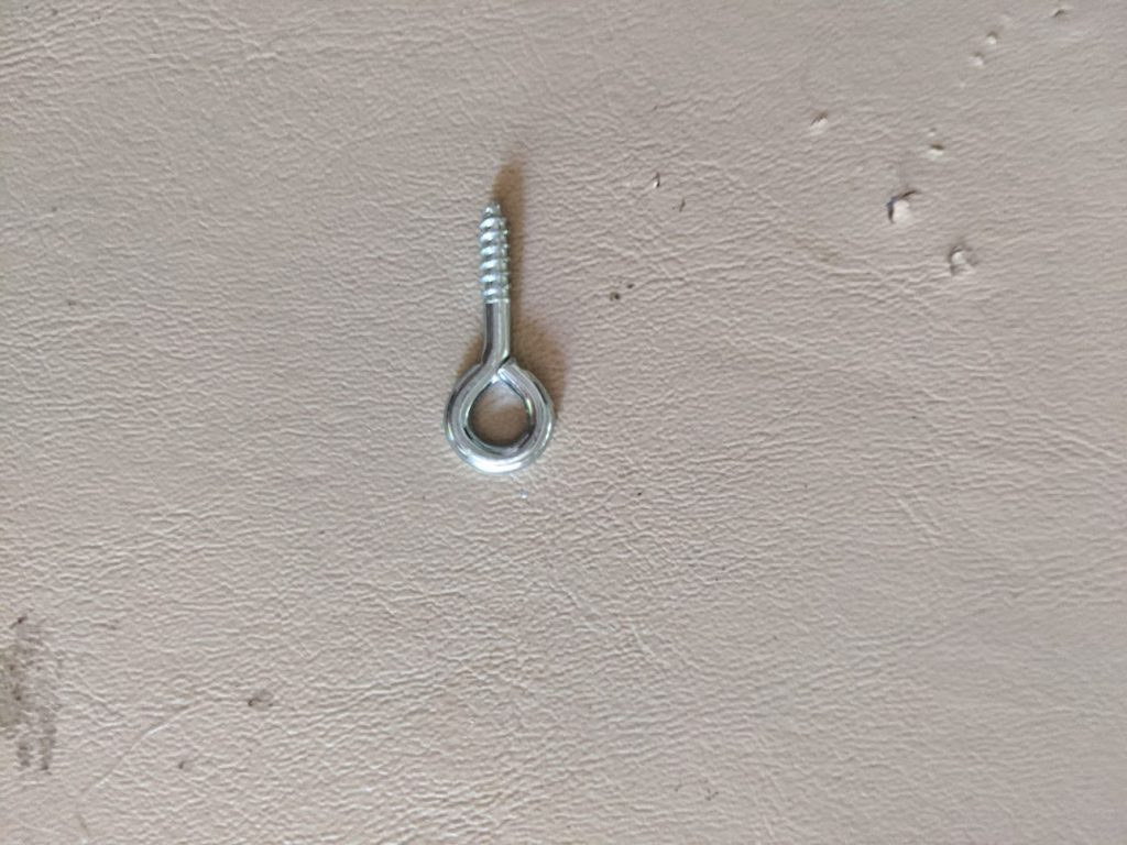
- Screw Eye Medium – SE-M
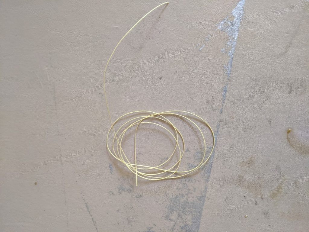
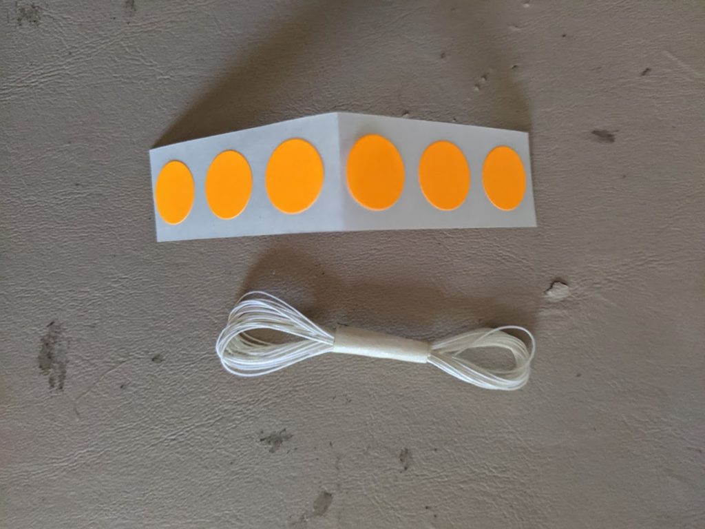
- Shroud Line – SLCA-96
- Kevlar Shock Line (90#) – SLK-90-36
- Tape Disks – TD-1-6
- Slug Fiber (2) – SGF-50
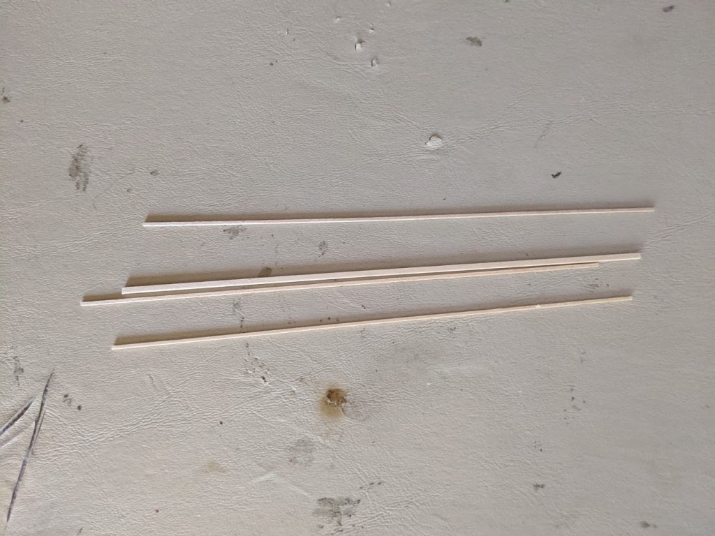
- Basswood (0.62″ SQ – SBW-62-62-6
- Basswood (0.40″) SQ (3) – SBW-40-40-6
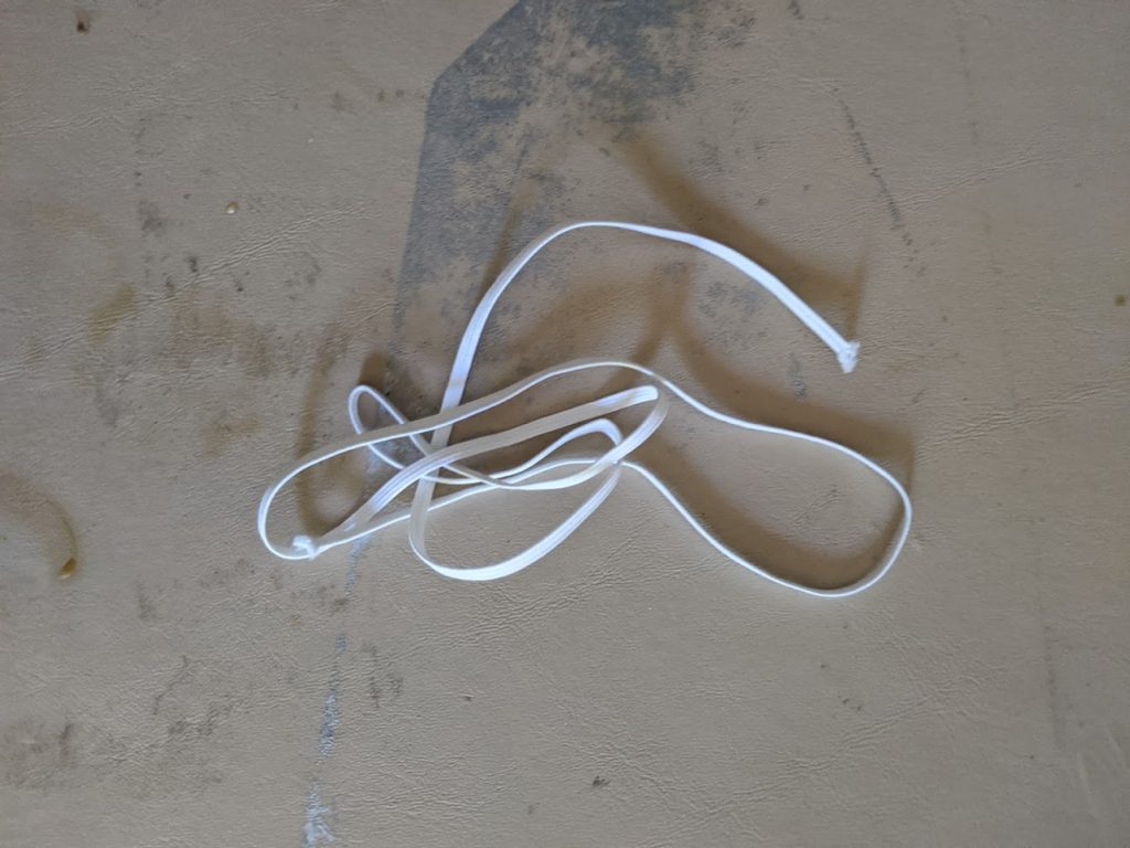
- Shock Cord Narrow – SC-1-24
- Decal Sheet – DCW-FR006
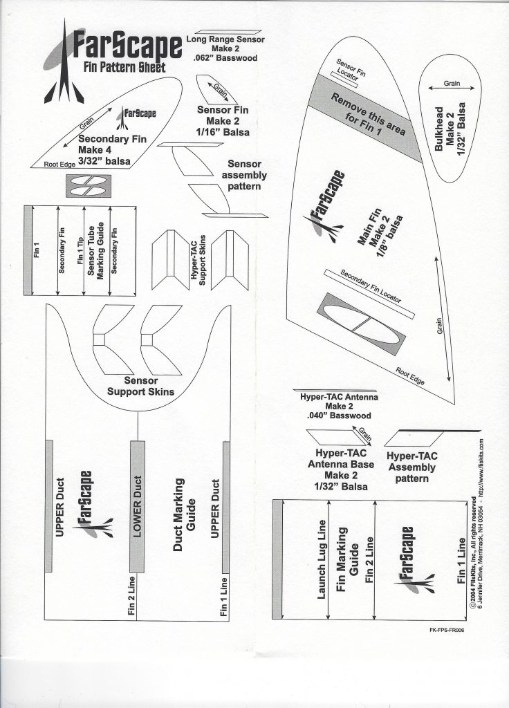
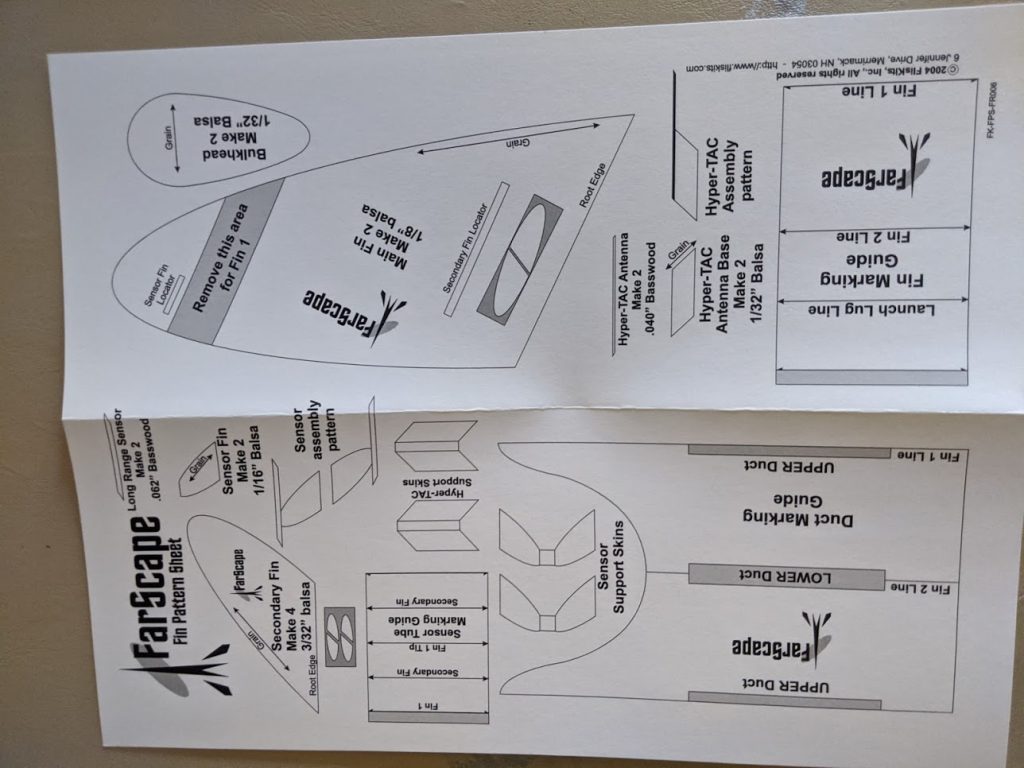
- Fin Pattern Sheet – FPS-FR006
- Instruction Sheet – INS-FR006
- Recommended Motors:
- B6-4, C6-5
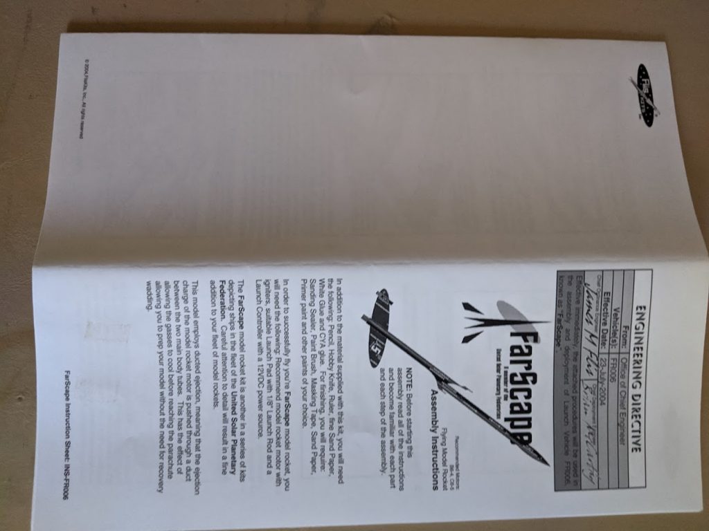
Instructions
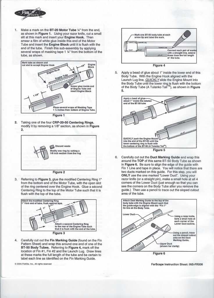
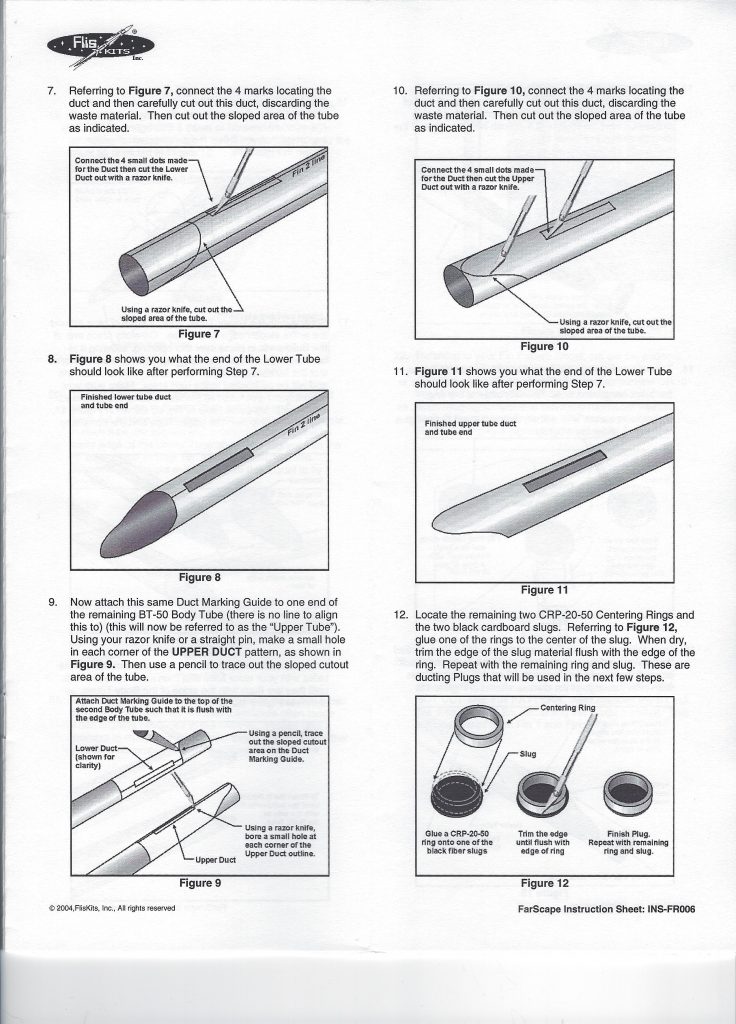
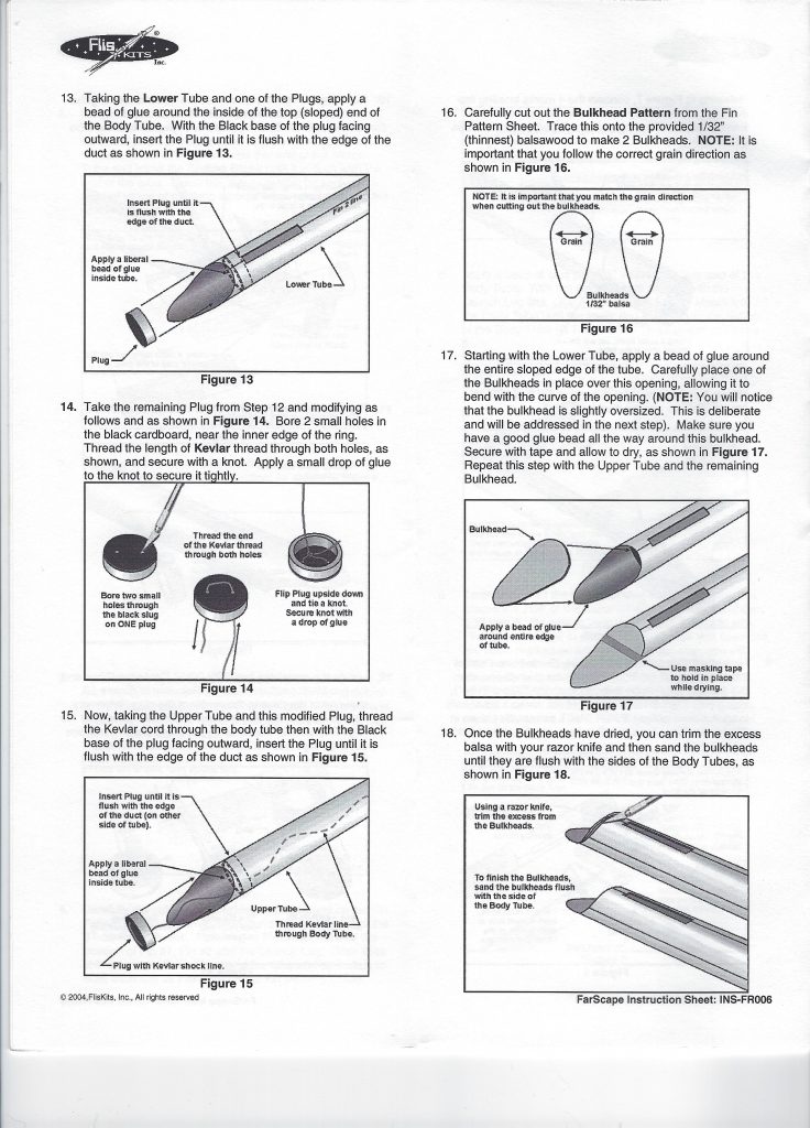
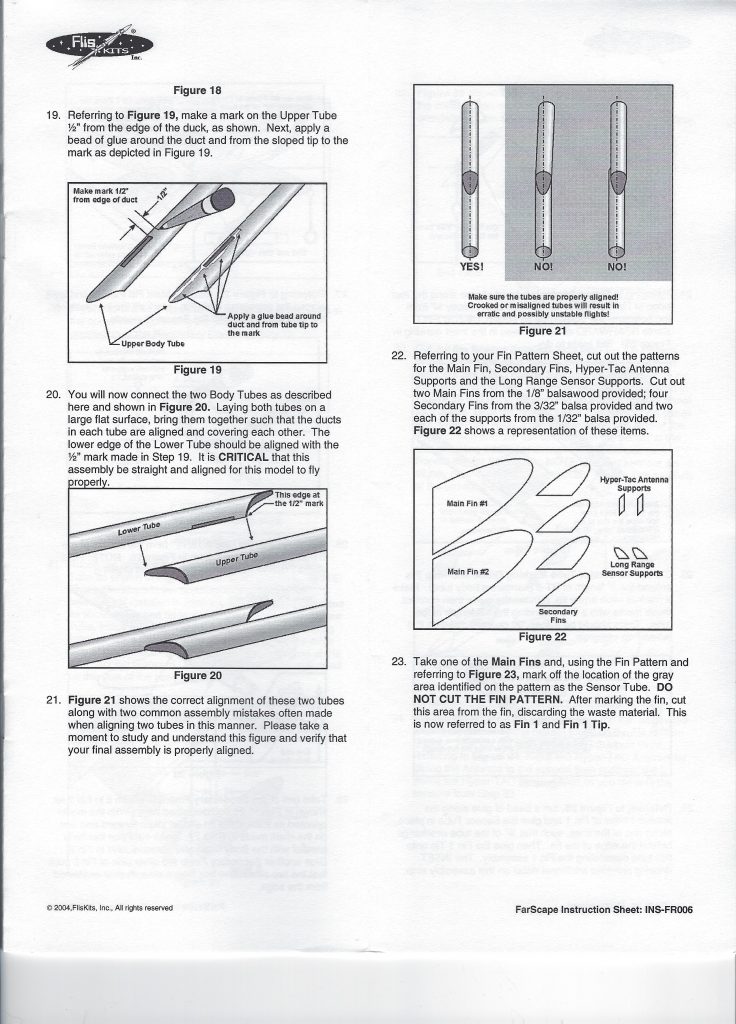
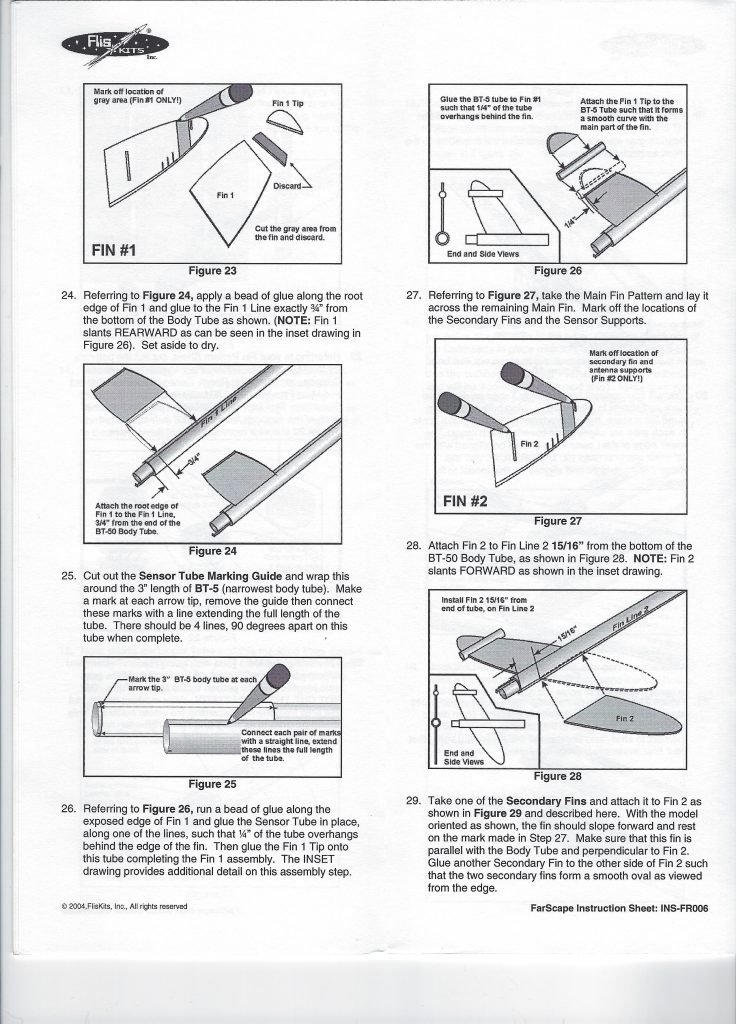
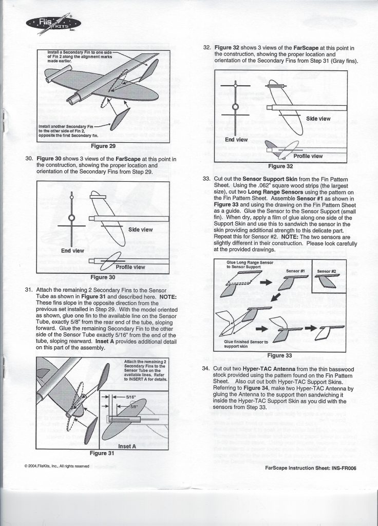
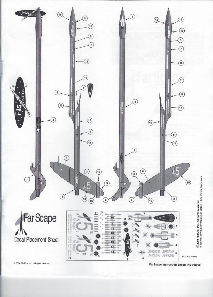
Photo Gallery


Build History
- 02/14/2005 – Purchased FlisKits FarScape from FlisKits for $14.95 (Retail – $21.95)
- 06/06/2020 – Took pictures of package and components. Scanned plans and components. Cut slit 1/4″ from forward end of motor mount tube and inserted engine hook into slit. Glued engine block into forward end of motor mount tube. Applied several wraps of masking tape 1-1/4″ from aft end of motor mount tube. Cut out 1/8″ section of centering ring and glued it 1″ from aft end of motor mount tube. Glued second centering ring even with forward end of motor mount tube.
- 06/07/2020 – Made copy of fin pattern sheet and cut out guides. Marked on body tube with launch lug and fin guide lines the entire length of body tube. Cut out duct marking guide.
- 06/08/2020 – Cut out top of body tube and marked tube with upper and lower ducts.
- 06/10/2020 – Glued shock cord to mount and then inside forward end of body tube at least 2″.
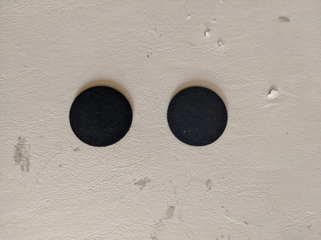
- 06/12/2020 – Cut out slots in body tube. Cut upper slot into upper body tube. Glued centering rings to black disks. Sanded smooth until they fit body tube. Glued disk and centering ring inside of body tube up to body tube slot edge. Punched two holes into disk and centering ring assembly and tied Kevlar through both holes securing the Kevlar knot with glue.
- 06/17/2020 – Cut out main fins, secondary fins, secondary fins and sanded to shape. Re-glued body tubes together. Filleted tube joint with epoxy paste.
- 06/18/2020 – Coated and smoothed tube seams with yellow glue. Cut out portion of fins #1. Glued fin 1. to body tube at fin #1 position. Glued body tubes to fin #1 and then glued fin tip to BT-5.
- 06/19/2020 – Glued fin #2 to fin #2 line of body tube.
- 06/23/2020 – Glued secondary fins to fins #2.
- 06/28/2020 – Glued secondary fins to BT-5. Cut 2 long range sensor fins 0.062″ from scrap wood and glued to sensor fin. Glued sensor support skins over long ranger sensors. Cut two Hyper TAC antenna skin to assembly. Glued sensor fins to fin line #2.
- 06/29/2020 – Glued sensor fins to fin 1. Glued Hyper TAC assemblies to upper and lower body tubes. Glued screw eye into nose cone. Made a shock cord mount and mounted shock cord to it. Mounted shock cord assembly inside upper body tube. at forward end of tube by 2″. Glued launch lugs at 1-=1/2″ and 7-1/2″ on launch lug reference line.
- 03/21/2021 – Spray painted with Krylon white primer.
- 10/13/2023 – Wiped model with alcohol wiper.
- 10/14/2023 – Due to a dent in the main body tube near the forward launch lug, cut the body tube off, inserted about 2″ f “D” engine casing inside of tube to strengthen it and glued tubes back together with the aid of a tube coupler and yellow glue. Filled joint with Tamiya putty and sanded the area smooth with 120, 220, & 600 grit sandpapers. Wiped with alcohol wiper.
- 10/15/2023 – pray painted entire model with Rust-oleum #327870 Gloss Black.
- 10/16/2023 – RFe-glued several pieces onto wings due to breakage. Touched-up black paint using T estors Black paint marker #2633.
Flights
| Date | Location | # | Motor | Comments |
Leave a Reply
You must be logged in to post a comment.